|
|
|
Categories
|
|
Information
|
|
Featured Product
|
|
|
 |
|
|
There are currently no product reviews.
 ;
I was having a hard time finding the problem with this Mackie 1604 unit. I didn't have a schematic. Went looking on the web and found your site and the price was more then reasonable. Ordered it and within the hour had the manual and within 15 minutes had the unit fixed. Best $4.99 I ever spent. Thank you.
Doug
;
This is a service manual in every sense of the word ( French and German versions of the text are included, as well as English..)
There are explanations of the mechanical and electrical functions, plenty of mechanical drawings, and the needed schematics. The quality of the scanning is excellent - all the component values are clearly legible - and very usefully there are pcb component layouts, so you can find a component on the schematic, and then very quicky pinpoint its physical location on the relevant pcb.
I cannot see how I can give this manual any less than the maximum 5 stars! Great value for money, which will pay for itself immediately. Excellent all round!
;
the manual is great and especially hard to find... thanks for the great service and having a hard to find manuel_
;
Please tell us what you think and share your opinions with others. Be sure to focus your comments on the product. You will receive $2.50 of store credit for Your review.
;
hat alles sehr gut geklappt. Das Servicemaual ist gut zu verwenden. Die Pläne und Schrift
ist klar und leserlich. Außerdem preiswert. Grüße an alle Hifi-Bastler
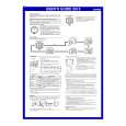
AV-21DMT3/AV-21D3 AV-2135TEE/AV-2135EE AV-21DMG3
SPECIFIC SERVICE INSTRUCTIONS
DISASSEMBLY PROCEDURE
REMOVING THE REAR COVER
1. Unplug the power plug. 2. As shown in figure, remove the
7
screws marked
!
and a
screw marked ". 3. Withdraw the rear cover toward you.
REMOVING THE MAIN PW BOARD
" After removing the rear cover. 1. Slightly raise the both sides of the MAIN PW BOARD by hand. 2. Withdraw the MAIN PW BOARD backward. (If necess ary, take off the wire clamp, c onnectors etc.)
REMOVING THE SPEAKER
" After removing the rear cover. 1. As shown in figure, remove the
2 screws marked # .
2. Follow the s ame steps when removing the other hand speak er.
CHECKING THE MAIN PW BOARD
1. To check the back side of the PW Board. 1) Pull out the MAIN PW Board. (Refer to REMOVING THE MAIN PW Board) 2) Erect the PW Board vertic ally so that you can easily check the back side of the PW Board. [CAUTION] " When erecting the PW Board, be careful s o that there will be no contacting with other PW Board. " Before turning on power, make sure that the CRT earth wire and other connector are properly c onnected.
WIRE CLAMPING AND CABLE TYING
1. Be sure to clamp the wire. 2. Never remove the c able tie used for tying the wires together. Should it be inadvertently removed, be sure to tie the wires with a new cable tie.
8
No. 52023
|
|
|
> |
|