|
|
|
Categories
|
|
Information
|
|
Featured Product
|
|
|
 |
|
|
There are currently no product reviews.
 ;
The manual was as described. Complete with parts list and technical information. Fast delivery.
 ;
Simple and fast...
The diagrams are clear and legible; i have been a great help.
The site is very reliable and precise thanks.
;
Very easy site. Great service and quick release for download. Manuals are of good quality.
Joop - The Netherlands
;
Very good manual, in depth and complete. Only criticism is that some of the circuit diagrams are slightly blurry and hard to follow for long periods of time, but this is to be expected. Perfect for any maintenance required. Also contains the wiring diagrams of the control cable for constructing extensions.
;
Received a quick response, material was exactly what it was supposed to be. The service did everything I expected it to do. would use service again.
1-2. Electrical Alignment
Preparation 1. Connect the equipment. 2. Extend the APR-31 board using the extension board EX-592. (Refer to �1-6. Use of Extension Board� in the Maintenance Manual for DSM-R1.) 3. Connect the coaxial cable and harness to the APR-31 board. Coaxial cable : CN600 (A-3) Harness (white) : CN900 (A-7) Harness (red)*1 : CN1000 (A-6)
*1 : Only when the rear panel with 5-pin XLR connector is used.
Adjustment Procedures 1. Supply 75% color-bar signal from the composite video signal generator to the VIDEO connector on the DSMT1. 2. Adjust RV600 (C-2) on the APR-31 board so that VIDEO OUT of the DSM-R1 is satisfied the specification. Adjustment : 1RV600 (C-2) Specification : A = 140.0 ± 1.4 IRE (A = 1.00 ± 0.01 Vp-p)
4. Return the menu setting data of the DSM-T1 and the DSM-R1 to the factory setting. (Refer to �3. To return the menu setting data to the factory setting� on the page 1-2.) 5. Turn on the power of the DSM-R1 and warm up the unit about 10 minutes. 6. Set the following menu for DSM-R1. (Refer to the �Menu Setup� in the Operation Manual for DSM-R1.) . �03 : VIDEO STD� : 525
A
1
5
4
9
8
3
2
A B C D E F G H J K L
7. Set the following menu for DSM-T1. (Refer to the �Menu Setup� in the Operation Manual for DSM-T1.) . �03 : VIDEO STD� : 525 8. Set the synthesized signal generator. . Frequency : 1270 MHz . Out Level : 0.0 dBm
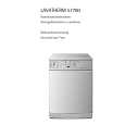
APR-31 board (A side)
7 6
RV600
11
1-8 (E)
BKSM-R103
|
|
|
> |
|