|
|
|
Categories
|
|
Information
|
|
Featured Product
|
|
|
 |
|
|
There are currently no product reviews.
 ;
This scanned manual is well done in that most all the pages except for one is straight and clear- the way I would do them. One page was upside down but that happens. For the money that is charged on this site you get a pretty good deal. Now with complex repairs, I still prefer to us paper manuals which I have to buy at stereomanuals but the one I got here was much less than the $45 he was charging but this is a larger than normal manual for three different units. I am a picky manual user because I have used original manuals from Sony and Teac.
;
Very useful service manual, was exactly what i needed.Good quality,reasonable price.Thank you.
;
Acurate informations inside the SM and I could repair my old Sansui SC-3330 without any problems. Thanks.
;
I used it to repair a NAD 7030, but unfortunately, the 7045 is different !
But documentation was useful.
;
Content A4 and A3 format pages. Exactly what I needed to restore my old receiver.
2-4. Software Update 2-5. Notes on Repair Parts
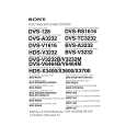
2-4-3. Flash Memory Replacement
1. Remove the top plate. (Refer to �2-1. Cabinet Removal/Installation�.) 2. Remove and replace the flash memory on the CPU244 board (IC7) using an IC extraction tool. Sony part number of IC extraction tool: J-6035-070-A n If the flash memory is difficult to be removed by the IC extractor, use the tweezers or equivalent.
2-5. Notes on Repair Parts
w Use the specified parts only Components marked ! are critical to safe operation. Therefore, specified parts in the section of Spare Parts should be used in the case of replacement. 1. Safety Related Components Warning Components marked ! are critical to safe operation. Therefore, specified parts should be used in the case of replacement. 2. Standardization of Parts Some repair parts supplied by Sony differ from those used for the unit. These are because of parts commonality and improvement. Parts list has the present standardized repair parts. 3. Stock of Parts Parts marked with �o� at SP (Supply Code) column of the spare parts list may be not stocked. Therefore, it may take a long time to deliver. 4. Units Representation The following represented units are changed or omitted in writing.
Units Capacitance Inductance Resistance Temperature uF uH Z dC Representation uF uH Abbreviation XXX-DEG-C
Flash Memory (IC7)
CPU-244 board
3.
While pressing the button 1 and 2 of the front panel at the same time, turn the power switch ON to initialize the unit. c If the unit is initialized, all setting data is back to default setting. Reset the setting or copy the data from another control unit. (For the details of setting, refer to the operation manual supplied with the unit.)
BKS-R1607/R1608 BKS-R3209/R3210
2-7(E)
|
|
|
> |
|