|
|
|
Categories
|
|
Information
|
|
Featured Product
|
|
|
 |
|
|
There are currently no product reviews.
 ;
I am satisfied with the service. And if need another manual, i will definitely buy from this site. Keep up the good work.
;
have download a number of manuals todate , most are excellant, one or two sometimes a little difficult to read but a least avaialable, great site .
Brad.
;
Excellent had everything I wanted, very happy with purchase
 ;
This service is relatively cheap, document is fast available, schematic is readable.
Thanks.
;
So far I´m a satisfied customer. I have only downloaded "TECHNICS SX-KN470 Service Manual" maybe I will use it later.
Best regards
Peter
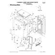
ELECTRICAL ADJUSTMENT-1/1
< TUNER SECTION >
1. AM IF Adjustment L007 ....................................................................... 530kHz
L003 BAR ANT
FRONT C.B
MAIN C.B
L007
3
CD C.B
2. AM VT Adjustment Settings: � Test point: C39 + � Adjustment location: L004 Method: Set to AM 1710kHz adjust L004 so that the test point becomes 5.5V±0.05V 3. AM Tracking Adjustment L003 ....................................................................... 600kHz TC001 ................................................................... 1400kHz
1
IC001 L005
4. FM VT Adjustment Settings: � Test point: C39 + � Adjustment location: L006
4
C39 L006
5
TC001 L004
Method:
Set to FM 108MHz adjust L006 so that the test point becomes 6.0V±0.05V
2 24
5. FM Tracking Adjustment L005 ........................................................................ 98MHz
3 9
SFR430
< TAPE SECTION >
6. Bias frequency Adjustment L330 ............................................................. 56kHz ±2kHz 7. Tape speed Adjustment Settings: � Test tape: MT111 � Test point: PHONES JACK (J251) � Adjustment location: SFR761 Method: Play back the test tape and adjust so that the output frequency is 3000Hz ±30Hz. 8. Azimuth Adjustment Settings: � Test tape: TTA-320 � Test point: PHONES JACK (J251) � Adjustment location:Azimuth adjustment screw
L330
6
SFR761 J251
7
Method:
87
Play back the 8kHz signal of the test tape and adjust screw so that the output becomes maximum.
JACK C.B
RPH/PH
< CD SECTION >
9. Focus Bias Adjustment Settings: � Test CD: TCD-782 (A-BEX) � Test point: IC401 PIN20, PIN58 � Adjustment location: SFR430 Method: Play back the #15 of the test CD and adjust SFR430 so that the voltage between pin20 and pin 58 of IC401 becomes 0V ±0.1mV.
8
-22-
 $4.99 CADW539 AIWA
Owner's Manual Complete owner's manual in digital format. The manual will be available for download as PDF file aft…
|
|
|
> |
|