|
|
|
Categories
|
|
Information
|
|
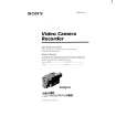
Featured Product
|
|
|
 |
|
|
There are currently no product reviews.
 ;
It was very usefull, it is clear the quality is super, the price I paid is very afordable.
Generally speaking Iam very happy with this company.
;
The manual was exactly what I needed, Good quality scans too. superb.
;
I am so happy found this site as it consists of so many Manuls and easy to aquire. This onei s exactly what I wanted and much more as it has info on not only how to use the tuner but how to repair it as well. I will come here 1st before purchasing else where! Thanks owner-manual.com!
;
Top class product, I printed it out on A3 paper and it is clear and very easy to follow.
Cheaper than buying a new radio!
;
is part of the manual is very useful for repairing
Here are circuit diagrams
if there is damage, I recommend using this part of the
a complete list of circuit boards and components
SERVICE NOTE
1. POWER SUPPLY DURING REPAIRS
In this unit, about 10 seconds after power is supplied (8.4V) to the battery terminal using the service power cord (J-6082-223-A), the power is shut off so that the unit cannot operate. This following three methods are available to prevent this. Take note of which to use during repairs. Method 1. Connect the servicing remote commander RM-95 (J-6082-053-B) to the LANC jack, and set the remote commander switch to the �ADJ� side. Method 2. Press the battery switch of the battery terminal using adhesive tape, etc. Method 3. Use the DC IN terminal. (Use the AC power adaptor.)
DC IN terminal Battery SIG terminal Battery terminal �
Battery switch
Battery terminal �
2. TO TAKE OUT A CASSETTE WHEN NOT EJECT (FORCE EJECT)
1 Refer to 2-1. to remove the front panel block. 2 Refer to 2-4. to remove the cabinet (R) assembly. 3 Refer to 2-6. to remove the battery panel block. 4 Refer to 2-7. to remove the cabinet (L) block. 5 Add +5V from the DC POWER SUPPLY and unload with a pressing the cassette lid.
6
Pull the timing belt in the direction of arrow A with a pinsette while pressing the cassette lid (take care not to damage) to adjust the bending of a tape.
A
Pinsette
Press the cassette lid not to rise the cassette compartment [DC power supply] (+5V)
Timing belt
7
Let go your hold the cassette lid and rise the cassette compartment to take out a cassette.
+
�
Loading motor Adjust the bending of a tape
Timing belt
�5�
|
|
|
> |
|