|
|
|
Categories
|
|
Information
|
|
Featured Product
|
|
|
 |
|
|
There are currently no product reviews.
 ;
This is a good quality scan of the Operation & Maintenance (Service) Manual for the PAL version of this high-band broadcast umatic, BVU-800P
All schematics and lineup procedures appear to be included in this one manual AFAICT.
The file size is just over 113 MB which gives an idea of the quality and number of pages.
All of the schematics, which contain some fairly small print, are easily readable when you zoom into the page.
John Thompson, Newcastle Upon Tyne, England.
;
Good quality, all schematics of few of models. There is also short form of user manual and regulation manual.
;
Perfect copy of the service manual. you can enlarge every page, and it comes up
with all details.
;
It´s very very nice manual with all, what i need. Original in good quality. Very fast business. Very much thanks...
;
Purchased the manual that I was looking for at a great price and could download it easily.. Great service experience and for future purchases I plan to use the site.
Thank you very much
1
2
3
4
A
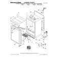
Notes on Replacement
Notes on replacing the Sheet SW
8 9
Mount the gear plate. Secure the gear plate, using the four screws. Gear plate
Place to adhere the Sheet SW
Notes: 1. Be careful not to warp the sheet SW. 2. Remove any dirt on the JOG holder to which the sheet SW is to be adhered. If some adhesive for the old sheet SW remains on the JOG holder, completely remove it with a cloth moistened with alcohol. 3. Do NOT place the sheet SW so that it is mounted on the rib of JOG holder 1000. 4. When adhering the sheet SW, be careful not to trap air bubbles in it. If air bubbles are formed, remove the sheet SW and adhere a new sheet SW. Do NOT reuse the removed sheet SW. 5. When making a connection, be sure to first release the lock of the connector then securely relock the connector after making the connection.
9 9 8
9
B
9
C
10 Remove the forced eject pin.
Forced eject pin
10
Sheet SW
D
11 Mount the cam plate. 12 Install the gear spring 200. 13 Mount the adjust plate. 14 Secure the adjust plate, using one screw.
Gear spring 200 JOG holder 1000 Rib
Place to adhere the SW cushions HH48/2
12 11
Adhere the cushions to the right and left of the engraved arrows (�) (12 positions in total) on the sheet SW.
E
Cam plate
14
Default value "0"
0
13
To increase the load
To decrease the load
+1 +2
-1 -2
SW cushion HH48/2
Engraved arrow
SW cushion HH48/2
-3
F
Note: For details on adjustment, see "Load Check mode for the JOG Dial."
Sheet SW Adjust plate
98
1 2
CDJ-1000MK3
3 4
|
|
|
> |
|