|
|
|
Categories
|
|
Information
|
|
Featured Product
|
|
|
 |
|
|
There are currently no product reviews.
 ;
It's a grate service manuals.Have many details and the writing it's so clear.You have all you want in manual,nothing missing,belive me.I'm verry satisfied of this manual.
;
Great scanned service manual
Usefull informations.
I will buy again!
Best Regards
;
The manual describes this product very good. It has the basic things to know and also a more detailed look. Very well made!
;
An excellent document to assist in the repair of my old personal tape player. It includes full circuit diagrams and physical layout drawings and full instructions on disassembly and fault finding.
Well worth the meagre price.
;
Very good conversation, Pretty fast Service, wood do it again,
Have paid by Paypal, so i got the Service Manual online after 15 Min.
Very helpfully.
Greeting from Germany,
Hans
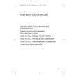
FM Polar Pilot Adjustment Setting : D-BASS switch : OFF SOURCE button : FM
FM RF signal generator antenna terminal set
MW Auto Scan/Stop Level Adjustment Setting : D-BASS switch : OFF SOURCE n MODE button : MW
30 � 15 pF 65 pF
Carrier frequency : 69.5 MHz (FM2 : 3CH) Output level : 60 dB (1 mV)
level meter main board TP1
+ �
AM RF signal generator
AM dummy antenna (50 �) set
Carrier frequency : 999 kHz 30% amplitude modulation by 1 kHz signal output level : 33 dB (44.7 µV)
antenna terminal
Procedure : 1. Connect the level meter to the TP1 on main board. 2. Set the modulation frequency of the FM RF signal generator to 1 kHz (10 kHz div.). 3. Then output level is supposing that 0 dB. 4. Set the modulation frequency of the FM RF signal generator to 31.25 kHz (10 kHz div.). 5. Adjust L604 so that the reading on the level meter becomes to maximum. 6. Adjust RV602 so that the reading on the level meter becomes to 13.0 ± 0.5 dB. Adjustment Location : See page 22.
Procedure : 1. Set to the test mode. (See page 19.) 2. Push the SOURCE button. 3. Push the MODE button and set to MW. Display
SHUF TP
4. Push the preset 3 button. Display
SHUF TP
5. Adjust with the volume RV1 on TU1 so that the �MW� indication turns to �MW0� indication on the display window. But, in case of already indicated �MW0�, turn the RV1 so that put out light �0� indication and adjustment. Display
SHUF TP
Adjustment Location : See page 22.
� 21 �
|
|
|
> |
|