|
|
|
Categories
|
|
Information
|
|
Featured Product
|
|
|
 |
|
|
There are currently no product reviews.
 ;
This is a great site. I placed my order and by the next am it was available for download. Had some problems with some missing copy on some pages. Once I brought the error to the OMC's attention, the issue was resolved. I'll come back again.
 ;
Mi spiace per non poter scrivere in inglese... ma sono veramente soddisfatto del servizio offerto. Grazie..!!
;
The quality of this manual is good. It has all schematics and setup information for both the MDS-B3 and the MDS-B4. The scan quality is quite good, all pages are readable, This service manual also contains scans of the operating instructions from the User manual.
;
Quick site processing. A complete and very useful manual with all details. Thank you!
;
Das Service Manual war von der ersten bis zur letzten Seite sehr informativ und hilfreich. Die Darstellung aller Teile war klar und der Text gut lesbar.
Vielen Dank, das war nicht der letzte Download bei ownner-manuals.com.
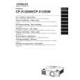
2. Wiring of the optical unit when it is mounted to the bottom case
Make sure to not tangle the cables when mounting the optical unit. Pull the CNLS cables to the rear so that they do not get caught in the gear cogs, after using the TAP2 to clasp them underneath the lens.
Connect the CNLS cables to the connectors that are besides the lens. Pass them underneath the lens as depicted in the diagram at right. They need to be configured so that they do not catch on the lens or the motor's gears. Connect the cable end that is closest to its binding Tapes to the connector beside the lens.
FRONT VIEW
CP-X1200(P5XLA) / CP-X1250(P5XMLA) / CP-X1200WA(P5XMLB)
Lens
Connect the CNRM cables to the ER01 remote control's connectors. * Attach the remote control CNRM board, the clasps and cover as per the assembly diagram.
TAP2 CNLS TAP2
Do not stress the flexible cable for the lens when wiring the CNLS cable.
Clasp underneath the lens
A83
Left speaker
Attach with the optical unit assembly.
#6607
CNLS
Fan for the red colored panel
Attach TAP 2, after configuring the cable in the approximate center of the clasp underneath the lens. (So that the gears of the motor do not catch, make sure that they do not get caught on the base of the lens when the lens is shifted downward.) Make sure that the CNLS connector is connected firmly and straightly to the connector beside the lens, after attaching TAP2.
31
Attach with the optical #6604 unit assembly.
Fan for the green colored panel
CNLS
CNLC
After connecting the CNME cable to the EY01 connectors for the dust sensor board, attach it to the optical unit.
CNME
Install the switchboard in the clasp in the optical unit assembly. The optical unit may be installed with CNLC cable connected to the E941 connector. Lever Protruding part
#6606
Fan for the blue colored panel
Attach with the optical unit assembly.
Signal board
Lamp fan
#680
Attach with the optical unit assembly.
Pass the CNLC cable underneath the protruding part of the clasp as depicted in the diagram to prevent the switch lever cable from becoming enclosed.
Cover the protruding portion of the clasp with tape. (As per the assembly diagram.)
Wiring diagram 3 (P5XLA/P5XMLA/P5XMLB)
|
|
|
> |
|