|
|
|
Categories
|
|
Information
|
|
Featured Product
|
|
|
 |
|
|
There are currently no product reviews.
 ;
perfect, i am very satisfait for the réception of the sansui r-5l service manual, thank you very much
;
Thank you, this is a rare document. Few others have it, but they charge way more for a download.
Great deal (even if you have to wait a few hours to get it).
;
The purchased manual is an high quality scan of the original Philips paper-based Service Manual. I am very satisfied!
 ;
The purchased manual is an scan of the original Panasonic paper-based Service Manual. Unfortunately the contrast is not perfect, but I am satisfied anyway!
;
The purchased manual is an high-quality scan of the original JVC paper-based Service Manual. The Service Manual includes the Owner´s Manual, so you do not have to buy both of them.
P501
30
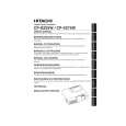
5. Wiring when the drive board is installed 1 Connect and lay the CNBAR cable and the connector #6222 cable. 2 Connect the CNTH, the CNPOW, the #6220 and the #6221. 3 Connect the CNRM, the CNLC and the #3020. 4 Connect the LC panel (R, G and B) flexible cables.
#6221
Procedure Before installing the drive board, connect the CNBAR and the #6222 with the drive board while holding them by hand. Pass the CNBAR lead through the cable guide on the ballast board cover. Put the drive board on its position and connect the CNTH, the CNPOW, the #6220 and the #6221 while lifting the drive board rear part. Finally, connect the CNRM, the CNLC, the #3020 and the flexible cables of the panels.
Circuit power supply cable Connect the cable to the E800 on the drive board. Panel B fan connector cable through the top of ballast cover as figure. (To prevent the B fan connector cable from the power supply is approached.) CNBAR cable through the cable guide on the ballast board cover.
Fan for panel G Connect the cable to the E803 on the drive board.
Thermistor cable Fan for panel R Connect the #6220 (connector color: black marking) CNTH cable to the CNPOW E302 on the Connect the cable to the E802 (black marking) on drive board. the drive board.
#6222
Fan for panel B Connect the cable to the E801 on the drive board Ballast control line cable
E803 E802
E302
E800 E801
CNBAR Connect the cable to the
E805 on the drive board. Lamp door switch cable
CNLC
P701
E805 E807
Connect the cable to the E807 on the drive board.
CNRM
E806
E804
P601
Remote control board cable Connect the cable to the E806 on the drive board.
CNSP
screw
Drive board assembly Connect the flexible cables of the panels to the flexible connectors (R to the P701, G to the P601 and B to the P501). 1 Pull out the hinge in the arrowed direction. 2 Insert the flexible cable under the hinge bottom. 3 Push the hinge in the arrowed direction. Hinge Flexible cable
#3020
Exhaust fan (connector color: black) Connect the cable to the E804 (black) on the drive board.
3 screws Caution when assembly the PWB Ass'y Drive Connect board to board connector on PWB Ass'y Drive and input firmly, before fixing 3 screws.
|
|
|
> |
|