|
|
|
Categories
|
|
Information
|
|
Featured Product
|
|
|
 |
|
|
There are currently no product reviews.
 ;
Everything okay, thanks a lot. It was a pleasure for me to make a deal with you.
;
A deal without problems, very fast and the manual is a good quality. Sorry for the my english.
;
Superb service and excellent quality of the document received
;
no problems with the purchase of a circuit diagram
;
Scan are good quality and overall just what i was looking for. Thanks!
CHAPTER 4 DISASSEMBLY/ASSEMBLY
5.7.2 Motherboard CPU
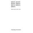
The CPU chip on the motherboard is installed in a socket (see F04-506-01 on page 4-20). The socket that holds the CPU on the motherboard is a Zero Insertion Force (ZIF) socket that allows the chip to be removed. Pin 1 on the ZIF socket is denoted by an angled corner. a. To Replace the CPU 1. Remove the CPU fan and heatsink as described in �To remove the CPU fan and heatsink� on page 4-32. 2. Lift the lever to release the CPU from the socket (see F04-507-03).
CPU Lever
Pin 1(angled corner on socket)
ZIF socket
F04-507-03 Removing the CPU 3. Grasp the edges of the CPU and gently pull it out of the socket. 4. Insert the new CPU so that the notch on the chip lines up with the notch area on the socket. Pin 1 on the CPU is denoted by an angled corner. The angled corner should point to the small 1 printed on the board directly below the CPU socket. 5. Push down the socket lever to secure the CPU. 6. Replace the CPU fan and heatsink as described in �To replace the CPU fan� on page 432.
4-24
COPYRIGHT© 2000 CANON INC. 2000 2000 2000 ColorPASS-Z40e/Z20e REV.0 AUG. 2000
|
|
|
> |
|