|
|
|
Categories
|
|
Information
|
|
Featured Product
|
|
|
 |
|
|
There are currently no product reviews.
 ;
Manual was destroyed and this purchase made it possible to recover my manual . It was easy to down load and smooth to use thanks .
 ;
Turns out this was not the manual i was looking for. The concertmate 670 keyboard i have is a "Realistic" model made for Radio Shack and none of the diagrams on the owners manual i received matches up. HOWEVER, I must say the service Owners Manual provides was fast and efficient by being available online. The manual was in good readable condition and easily downloaded.
;
Great price, Quick delivery, the document was very usefull A+++++++++++++++
;
Thank´s for your help, I already recived these manual from you
;
Thank you for your manual It has the basic things to and i use the Oszi for Longer Time.
THX
CT-34WX53
1.5.
Hold Down or Safety Circuit Information
1.6.
To monitor the high voltage, the positive DC voltage from the cathode D512 is applied through R1507 and other resistors to pin 3 of IC1501, which is the input terminal of the X-ray Protection Circuit. The voltage at pin 2 of IC1501 is 5.90 ± 0.03 voltage. Under normal conditions this voltage is insufficient to activate the X-ray Protection Circuit. If the voltage at pin 3 of IC1501 increases over the voltage at pin 2 of IC1501 increases and causes the X-ray Protection to activate. Then it causes the shut down works. In the process described above, the voltage at pin 3 of IC1501 is compared with the voltage at pin 2 of IC1501.if excessive beam current is drawn, the voltage at pin 3 of IC1501 increases. When the voltage at pin 3 of IC1501 over the voltage at pin 2 of IC1501, the voltage at pin 1 of IC1501 becomes "high" and feeds into pin 45 of micro-controller IC4002 through R4084.The micro-controller then turns off Q802, causes the AC power relay RL801 to unlatch and turns off the receiver. Purpose
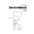
Service Instruction: Procedure to apply silicone to the seal control VR538 and VR524
To prevent any adjustment on the sealed control after final adjustment is done at factory. If the sealant are removed for any reason, the control is damaged at same time. Material 1. Silicone-Type T8C1710201H, manufactured by ShinEtsu Chemical Co., Ltd. (Japan) 2. Hard ABS tube-Type TMMX004 Tools No tool is required. Procedures 1. Place the hard ABS tube on the designated sealed control, as shown in Figure a.
Figure a.
2. When the tube is gently pressed all the way down and adhere to the P.C.B., apply the silicon into the hard ABS tube and form hemisphere like object on the top of tube, as shown in Figure b.
Figure b.
4
|
|
|
> |
|