|
|
|
Categories
|
|
Information
|
|
Featured Product
|
|
|
 |
|
|
There are currently no product reviews.
 ;
It was just what I need to fix my old BMW's CD player. Very convenient also. Thank you.
;
Great Manual! It contains all the wiring schematics and mechanical exploded views that are essential for service and repair. I was surprised I even found this for such an old machine. Only wish I knew of this site many years ago.
;
Great manual very clear copied. You are making an incredible job. I appreciate a lot the rapidity and your efficiency. Thanks a lot
;
Good pdf of the service manual for this unit. Includes disassembly instructions, full schematics, board layouts, parts lists and diagnostic information. Some information is in the pdf twice (single pages, and split pages), but that could be how it was originally generated by panasonic, or perhaps the idea is to make it eaiser to put onto 8.5 x 11" pages.
Information was exactly what I needed. Delivery was overnight (less than 12 hours) and I was happy with the process.
;
5 STARS for FAST DELIVERY, BEST PRICES and QUALITY PRODUCT. Item was exactly as described with superb resolution. Will definitely source all my future requirements from this website. Thanks a lot owner-manual.com!
4-3. Drum Base Assembly, Drum Earth
1. Removal procedure
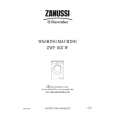
1) Remove the capstan flexible board and flexible wiring board (FP-300) from the holders X, Y and Z in the direction of the arrow. Remove the drum assembly. (Refer to section 4-1.) Remove the screw (M1.4 � 2.5) 2. Remove the claw D of the guide rail T2 3 from the hole E of the drum base assembly in the direction of the arrow F. Remove the three screws (M1.4 � 2.5) 4. Remove the drum base assembly 5 in the direction of the arrow. Remove the screw (screw assy PW M1.7 � 2.6) 6. Remove the drum earth 7 and earth spacer 8.
2. Attachment procedure
1) Attach the ground spacer 8 and drum ground 7 with the screw (screw assy PW M1.7 � 2.6) 6. Tightening torque: 0.078 ± 0.01 N�m (0.8 ± 0.1 kgf�cm) Align the drum base assembly 5 with the reference pin and tighten the three screws (M1.4 � 2.5) 4 in the order of G, H and I. Insert the claw D of the guide rail T23 into the hole E of the drum base assembly 5 and tighten the screw (M1.4 � 2.5) 2. Tightening torque: 0.078 ± 0.01 N�m (0.8 kgf�cm) Remove the drum assembly. (Refer to 4-1.) Attach the flexible wiring board (FP-300) 1 and capstan flexible board to the drum base assembly. Clean the tape running path. (Refer to 2-2.)
2) 3) 4) 5) 6) 7) 8)
2)
3)
4) 5) 6)
G F
hole E
H I 4 Three screws (M1.4 � 2.5) 5 Drum base assembly
2 Screw (M1.4 � 2.5)
Guide rail (T2) Remove the guide rail (T2) in the direction of the arrow F.
Claw D
Drum base assembly
3 Guide rail (T2)
Remove the flexible board in the direction of the arrow A B C. FP-300 flexible board
C B 6 Screw (screw assy PW M1.7 � 2.6) 7 Drum ground Z Y X A 8 Ground spacer
Two dowels
Claw D
Capstan flexible board
1 FP-300 flexible board, Capstan flexible board
Fig. 4-3.
� 16 �
|
|
|
> |
|