|
|
|
Categories
|
|
Information
|
|
Featured Product
|
|
|
 |
|
|
There are currently no product reviews.
 ;
Payments were processed quickly and items were exactly as described. I will use owner-manuals.com in the future for any other manual needs.
;
The Technics manual was very clear and I was able to solve my technical problems.
I did not think that anyone kept these manuals and was pleasantly surprised to find them on the Internet and at an affordable price.
I would recommend Owner Manuals as a first source of technical products for ‘dated’ equipment manuals.
Ian
;
The content of the manual was not found on the Internet and was a hard find. I check the net for 5 hours until I came across this web-site. When I did find the book it Auto loaded into my IPAD PDF shelf for books for review at anytime. Overall I am satisfied with the book and it answered all my questions. This repair book is obsolete because the product I bout it for is pretty old. Thanks for the help with the download and even having the manual. Thanks 73's K5HRD
;
Excellent manual including schematics. The service was great and the manual helped complete the job.
;
It was magic after so many years to still be able to source this info. It was equally amazing to return my Pioneer receiver to it near new sound quality AFTER NEARLY 30 YEARS! Thank you for this ability!
D-E350/E351/E351SR/E353/E355/E356CK SECTION 1 SERVICING NOTES
NOTES ON HANDLING THE OPTICAL PICK-UP BLOCK OR BASE UNIT The laser diode in the optical pick-up block may suffer electrostatic breakdown because of the potential difference generated by the charged electrostatic load, etc. on clothing and the human body. During repair, pay attention to electrostatic breakdown and also use the procedure in the printed matter which is included in the repair parts. The flexible board is easily damaged and should be handled with care. NOTES ON LASER DIODE EMISSION CHECK The laser beam on this model is concentrated so as to be focused on the disc reflective surface by the objective lens in the optical pick-up block. Therefore, when checking the laser diode emission, observe from more than 30cm away from the objective lens. Before Replacing the Optical pick-up Block Please be sure to check thoroughly the parameters as per the �Optical pick-up Block Checking Procedure� (Part No. : 9-960-027-11) issued separately before replacing the optical Pick-up block. Note and specifications required to check are given below. � FOK output : IC601 yg pin When checking FOK, remove the lead wire to disc motor. � RF signal P-to-P value : 0.45 to 0.65Vp-p Laser Diode Checking Methods During normal operation of the equipment, emission of the laser diode is prohibited unless the upper panel is closed while turning ON the S801 (push switch type). The following two checking methods for the laser diode are operable. Method : Emission of the laser diode is visually checked. 1. Open the upper lid. 2. Push the S801 as shown in Fig. 1 . 3. Check the object lens for confirming normal emission of the laser diode. If not emitting, there is a trouble in the automatic power control circuit or the optical pick-up. During normal operation, the laser diode is turned ON about 2.5 seconds for focus searching.
S801
Fig.1 Method to push S801
SECTION 2 GENERAL
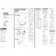
LOCATING THE CONTROLS
This section is extracted from instruction manual.
DC IN 4.5V
>B
ESP
.
OPEN
x
i
MENU
VOL�
HOLD . VOL+ SOUND
DISPLAY
3
|
|
|
> |
|