|
|
|
Categories
|
|
Information
|
|
Featured Product
|
|
|
 |
|
|
There are currently no product reviews.
 ;
- Very good scan quality, PERFECT!
- Sehr gute scan Qualitaet, empfehlenswert!
Wolfgang Sundhaus
 ;
Good site, works ok and you get what you order, no problems experienced, got my manual within a day. A++++
;
Original well scanned manual. Got the job done. Microwave problem found & corrected. For $5 and a new magnitron from ebay, it was a cheap and good the first shot fix. Electrical schematics allowed me to mage sure every thing else was ok before cutting and order for parts. Hard to live without.
;
I was very skeptical of this website, I have never downloaded manuals before. I put it on the AMEX and payed through Paypal to ensure protection. I got the manual exactly as described and now I can replace the filter capacitor for this amp. Great Price, others selling for 12.99 or more and this is the same manual. I will search out this website for other manuals. Thank you
;
Manual was reasonably easy to follow. I am not an engineer or know much about electronics but with the manuals help I was able to figure out the problem, identify the part required for the repair. Replacement part cost around $30. Whilst replacing the part I was telling myself, "this aint gonna work cos it seems far too easy". Took about 15 minutes to do and my plasma TV works a treat. Would never have been able to do this without the service manual.
5
6
7
8
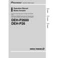
3. DISASSEMBLY
- How to hold the Mechanism Unit
1. Hold the top and bottom frame. 2. Do not squeeze top frame's front portion too tight, because it is fragile.
A
B
Do not squeeze.
- Removing the Upper and Lower Frames
1. With a disc clamped, remove the four springs (A), the two springs (B), the two springs (C), and the four screws. 2. To remove the upper frame, open it on the fulcrum A. 3. While lifting the carriage mechanism, remove the three dampers. 4. With the frames removed, insert the connectors coming from the main unit and eject the disc. Caution: Before installing the carriage mechanism in the frames, be sure to apply some alcohol to the dampers and set the mechanism to the clamp mode. Carriage Mechanism B Damper Lower Frame B Damper A Damper C
D
A C A
Upper Frame
A
C
A
- Removing the Guide Arm Assy
1. Remove the upper and lower frames and set the mechanism to the clamp mode. 2. Remove the two springs. 3. Remove the two screws and bevel gear bracket. Note that the gears come off. 4. Slide the guide arm assy in the direction marked Spring with the arrow (1) and open it upwards. 5. At the angle of about 45 degrees, slide the guide arm assy in the direction marked with the arrow (3) to remove it.
E
F
Guide Arm Assy
Spring
CX-3110
21 7 8
5
6
|
|
|
> |
|