|
There are currently no product reviews.
 ;
Super manual it contains all the things you need to service your Marantz 2100.
;
A very easy to understand and use manual. Well worth the money.
 ;
Very good information with clear drawings. Thanks!
;
The ease of this purchase was a good start. The content of this manual was exactly all I needed to retore my Tandberg 64.
All of the mechanical and electrical information is contained in the manual and the quality of the document makes reading the data easy.
The exerience with the resource has made this my prime source for technical data.
;
Owner-manuals.com is the best Possibility to give vantage HIGH CLASS Elektronic COMPONENTS
a new Life.Thanks alot for your perfekt Service.
DEH-P410,P4100,P310
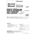
- Removing the Guide Arm Assy
1. Remove a connector, a spring A and B 2. Drive the Guide Arm Assy up aslant into rear side direction, then remove it from a Pin. Finally, drive the assembly approximately 45 degrees upward, then slide the assembly toward left side to remove it. Note : When assembling the guide arm assembly, route the cord inside the assembly. In this operation, care must be exercised so that cord may be caught by the gear.
Guide Arm Assy Section
A
B Pin
LO Arm Assy Section
- Removing the LO Arm Assy
1. Remove two Pins to dismount the LO Arm Assy.
- Removing the Control Unit and the Spindle Motor
1. Remove from the connector after mounting the short pin on the flexible PCB of the pickup unit. 2. Remove two Soldered joints, then remove two Screws A. 3. Remove two connectors and a Screw B. 4. Disengage the Control Unit from two Tabs, then dismount the unit by sliding it toward left. 5. Dismount the Spindle Motor.
Short Pin
Spindle Motor
B
Control Unit
A
A
68
|