|
There are currently no product reviews.
 ;
Excellent scan quality. A complete and very useful manual with all details.
Great service at low price A+++++++++++++++++
;
The manual is very good quality. very good graphics. complete
;
Excellent printing quality.
A complete and very usefull service manual with all details.
GREAT SERVICE AT VERY LOW PRICE!
A+++++++++++++++++++++++++
;
Excellent, very professional, fast, reliable, congratulations thank you.
;
Excellent printing quality.
A complete and very usefull service manual with all details.
GREAT SERVICE AT VERY LOW PRICE!
A+++++++++++++++++++++++++
5
6
7
8
3. DISASSEMBLY
- How to hold the Mechanism Unit
1. Hold the top and bottom frame. 2. Do not squeeze top frame's front portion too tight, because it is fragile.
A
B
Do not squeeze.
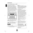
- Removing the Upper and Lower Frames
1. With a disc clamped, remove the four springs (A), the two springs (B), the two springs (C), and the four screws. 2. To remove the upper frame, open it on the fulcrum A. 3. While lifting the carriage mechanism, remove the three dampers. 4. With the frames removed, insert the connectors coming from the main unit and eject the disc. Caution: Before installing the carriage mechanism in the frames, be sure to apply some alcohol to the dampers and set the mechanism to the clamp mode. Carriage Mechanism B Damper Lower Frame B Damper A Damper C
D
A C A
Upper Frame
A
C
A
- Removing the Guide Arm Assy
1. Remove the upper and lower frames and set the mechanism to the clamp mode. 2. Remove the two springs. 3. Remove the two screws and bevel gear bracket. Note that the gears come off. 4. Slide the guide arm assy in the direction marked Spring with the arrow (1) and open it upwards. 5. At the angle of about 45 degrees, slide the guide arm assy in the direction marked with the arrow (3) to remove it.
E
F
Guide Arm Assy
Spring
CX-3098
21 7 8
5
6
|