|
|
|
Categories
|
|
Information
|
|
Featured Product
|
|
|
 |
|
|
There are currently no product reviews.
 ;
Very good manual. Plenty of service information including alignment instructions. Clear circuit diagram. Excellent, thank you.
 ;
Good morning, the service manual you sent me was perfect.
Your service and answering are excellent.
I recomend this service.
Best regards.
;
I had been looking everywhere for a proper service manual for this VCR. Everywhere else that has this available for download has a very light version. This is the full service manual with all aspects that would interest anyone looking for the service manual for the AIWA HV-MX100 Worldwide VHS VCR. Great quality (as always). A winner hands down. Best Quality.
;
Top quality manual. Covers all aspects you'd expect in a top quality service manual for this Panasonic VHS VCR. The manual resolution is high. Another top quality manual from the only site worth downloading manuals from! If you're looking for a manual for the PV-9662 VHS VCR, this is the one you'll want to get!
;
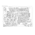
complete part-lists and pcb layout, schematic diagram is good enlargable,
APPENDIX IC DESCRIPTION
13
PIN NAME CW OUT
FUNCTION An output terminal for the continuous chroma sub-carrier frequency wave, with an amplitude of 0.7Vp-p (typ). Also the dc level shows chroma killer status, with a level of 3.5V for B/W and 1.5V for Color.
INTERFACE
14
RGB VCC(9V)
15
YS/YM SW /Spot killer
A Vcc terminal for RGB block, PIF det. Output and sound output circuit. Supply 9V. A terminal for switching of EXT RGB Mode and fast Half tone.
-
16 17 18
EXT.R IN EXT.G IN EXT.B IN
Input terminals for EXT RGB signals. The signals are clamped by capacitors, therefore the input impedance should be low, 100 ohms or less is recommended. For this input, the brightness and RGB contrast is adjustable, the ABL/ACL limits the output level. This ABL/ACL may be turned On and OFF. OFF : for small area like OSD ON : for large area like TELETEXT (input level 0.7Vp-p/100IRE) The GND terminal for Y/C circuit. Terminals for R/G/B signal output. Connect resistances to GND, for the current source if the slew rate is not enough. Due to the source current limitation, the resistances should be 2.0 or more.
19 20 21 22
Y/C GND R OUT G OUT B OUT
-
-6-
|
|
|
> |
|