|
|
|
Categories
|
|
Information
|
|
Featured Product
|
|
|
 |
|
|
There are currently no product reviews.
 ;
Thank you very much you are helping me a lot with my preferred hobby!!! this manual of an old TV is going to be very helpful!!!!
You are very honest competent great job very clear and well done!!!!
Matteo
;
An excellent service manual contains dismantling locations of components, electronic adjustments,worth the money.
;
Caracteristiques,circuit adjusment,notes on schematis diagram,it's a good service manual,to live well,thanks.
;
Service Manual in good quality, with all of the pages.
;
Very usrfull for repaur, great quality copy. includes complete parts list and schematics
For fast insertion on RIN, GIN, BIN inputs then brightness, contrast and white point RGB is possible
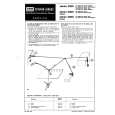
RGB output illustration during OSD mode During OSD, the DC level on RGB outputs is 200mV less then DC level on RGB outputs during black current measurement (contrast, brightness and white point RGB are inactive) � Blue stretcher The Blue stretcher can be divided into two stretch-frunction - the Standard blue stretcher - the Extended blue stretcher The blue stretcher reduces the R- and G- signals by 14% whenever the video signal exceeds a threshold level of 80%. The extended blue stretch With the extended blue stretch the reduction of the G-signal is 8% and for the R-signal it is 22% whenever the signal exceeds the threshold level of 80% When adjusting the white point be sure that the blue stetcher is inactive. In principal all features should be switched off during white point adjustments. � RGB output stages. Looking at the RGB output signals several DC-levels can be seen. The DC-levels of the H- and V-blanking are 0.5V below nominal black level of the video signal. At the end of the vertical blanking (line 19, 20, 21) the measuring pulses for Continuous Cathode (CCC)loop or two point black current stabilisation can be observed. These measuring pulses have three DC-levels: - A DC-level of-0.1V with respect to nominal black level during the leakage measurement (LO). This level is chosen so that it lies close to the black level in order to have an accurate measurement close to cut off voltage of the picture tube - A pulse of +0.25V with respect to nominal black level, which corresponds with a cathode current of 8µA - A pulse of 0.38V above nominal black level which corresponds with a cathode current of 20µA The pulse-levels of +0.25V and +0.38V can only be seen measured on alternating fields. The RGB blanking level tracks with the DC level of the black current measurement pulses. The RGB output stages supply the buffered RGB signals to pins 21, 20 and 19 respectively.
43
|
|
|
> |
|