|
|
|
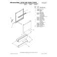
Categories
|
|
Information
|
|
Featured Product
|
|
|
 |
|
|
There are currently no product reviews.
 ;
It is great, it saves money and paper. It helps me to save room and recources.
;
manual service is ok , resolve the problems
manual service is ok , resolve the problems
manual service is ok , resolve the problems
manual service is ok , resolve the problems
manual service is ok , resolve the problems
 ;
Well I got all the necessary specifications for the job. Document of good quality and good definition of the diagrams
;
hi .full information for JVC GRVF1EG Service Manual its compete .Thank You
;
perfect and good copies, all good readable.
within 24hrs and very cheap also.
DVR-7000
Mark
Video I/F
Pin Name
I/O
Pin Function
Video PTS Clock. This required clock is timing reference for the internal presentation timestamp (PTS) counter. The external PTS clock frequency is either 27 MHz or 90 kHz. The internal frequency is 90 kHz. Microcode autodetects the PTS clock frequency and adjusts its internal divider appropriately. PTSCLK is asynchronous to all other processor clocks. C-Cube recommends that your board include parallel AC termination or DC termination to terminate this clock's source driver. Video Clock. VCLK is the video input/output sampling clock. Input data is sampled and output data is driven on the rising edge of VCLK. Valid VCLK frequencies are 27 MHz and 54 MHz. VCLK is asynchronous to all other processor clocks. Video input Data. These pins capture the interleaved luma and chroma samples (4 : 2 : 0 format). Micro-code determines whether the data order is (Cb, Y, Cr, Y) or (Y, Cb, Y, Cr). The DVxcel processor decodes the SAV codes in the incoming video data to determine whether the video is active and whether the field is odd or even. For 8-bit input, drive data onto pins VI_D [9 : 2] and ground pins VI_D [1 : 0]. Video Input Enable. When VI_E is asserted, the DVxcel processor samples input pels on the VI_D bus and increments the horizontal position counter. This signal allows external downsampling hardware to throttle video capture without generating a nonstandard video clock.
PTSCLK
M1
I
VCLK
T20
I
VI_D [9 : 0]
M20, M19, M18, N20, N19, P20, N18, P19, R20, R18
I
VI_E
P18
I
VO_ACTIVE
R19
O Video Output Active. The DVxcel processor asserts VO_ACTIVE when an active TS (nonblanked) pel is present on the VO_D bus. VC
VO_D [7 : 0]
Video Output Data. The DVxcel processor outputs interleaved luma and chroma samples (4 : 2 : 0 format) on these pins. Microcode detemines whether the data order is either (Cb, Y, Cr, Y) or (Y, Cb, Y, Cr). The DVxcel processor inserts an O U19, V20, T19, V19, W20, SAV code with the appropriate V and F bits into the output stream starting four TS W19, U18, Y20 clocks before VO_ACTIVE is asserted. The V bit in the SAV code is set to one VC during vertical blanking. The F bit is set to one when the current field is even. The DVxcel processor inserts an EAV code into the output stream starting on the clock that VO_ACTIVE is deasserted. Video Output Enable. When VO_E is asserted, the output value and horizontal position are held to the same value as in the previous clock, if the video output was not blanked during that clock. VO_E allows external hardware to throttle video output without generating a nonstandard video clock. VO_E is ignored with echo active. VO_E can be used with genlock or video capture active as long as the time to transfer the last active pel is less than the total input frame time.
VO_E
V18
I
VO_HSYNC
U20
Video Horizontal Synchronization. The DVxcel processor asserts VO_HSYNC at the O first pel in each line for the duration specified by the microcode. Note that the TS polarity of this output is programmable via the OSPOL bit in the Video Control VC Register. Video Vertical Synchronization. The DVxcel processor asserts VO_VSYNC at the beginning of an odd field and holds it assrted for the number of lines specified by O the microcode. For interlaced transfer, the processor asserts VO_VSYNC starting in TS the middle of the last scan line of an odd field. VO_VSYNC is then deasserted in VC the middle of the scan line after the number of lines specified by the microcode (next even field). Note that the polarity of this output is programmable via the OSPOL bit in the Video Control Register.
VO_VSYNC
T18
125
|
|
|
> |
|