|
|
|
Categories
|
|
Information
|
|
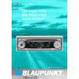
Featured Product
|
|
|
 |
|
|
There are currently no product reviews.
 ;
hat alles sehr gut geklappt. Das Servicemaual ist gut zu verwenden. Die Pläne und Schrift
ist klar und leserlich. Außerdem preiswert. Grüße an alle Hifi-Bastler
;
I got the manual quickly after the payment was transfered (1 day). The manual was exactly what i needed and the updates via e-mail were great. Thanx!
;
I've looked for this manual all over that internet, you guys had it and to a good price. A++++
;
I've looked some time for this manual, you guys had it and to a good price. A++++
 ;
factory technician level - complete with board views :
( removing chassis from cabinet , only thing missing ) ;
on weekends , staff is not available so - be patient .
3.1.9 Removing the amplifier 1 and amplifier 2 boards (See Fig.17 to 19) [For DX-T9] � Remove the metal cover, tuner, fan, rear panel and main board. (1) (1)From the right side of the main body, remove the screw N attaching the earth wires to the bottom chassis. (See Fig.17.) Reference: After reassembling, fix the earth wires with the spacer as before. (See Fig.17.) (2) Disconnect the amplifier 2 board from the bridge board in the direction of the arrow while releasing the claw j of the connector CN200 on the bridge board. (See Fig.17.) (3) (3)From the left side of the main body, disconnect the card wire from the connector CN303 on the amplifier 1 board. (See Fig.17.) (4) Disconnect the amplifier 1 board from the bridge board in the direction of the arrow while releasing the claw k of the connector CN201 on the bridge board. (See Fig.18.) Note: When releasing the claws (j, k), take care not to break them. (See Figs.17 and 18.) Take out the amplifier 1 board and amplifier 2 board together from the main body. Remove the two screws P and remove the leaf spring. (See Fig.19.) Remove the two screws P and remove the amplifier 1 board from the heat sink. (See Fig.19.) Remove the four screws P and remove the amplifier 2 board from the heat sink. (See Fig.19.)
3.1.11 Removing the amplifier 1 and amplifier 2 boards (See Fig.17 to 19) [For DX-T5] � Remove the metal cover, tuner, fan, rear panel and main board. (1) From the right side of the main body, remove the screw N attaching the earth wires to the bottom chassis. (See Fig.17.) Reference: After reassembling, fix the earth wires with the spacer as before. (See Fig.17.) (2) Disconnect the amplifier 2 board from the bridge board in the direction of the arrow while releasing the claw j of the connector CN200 on the bridge board. (See Fig.17.) (3) From the left side of the main body, disconnect the card wire from the connector CN303 on the amplifier 1 board. (See Fig.17.) (4) Disconnect the amplifier 1 board from the bridge board in the direction of the arrow while releasing the claw k of the connector CN201 on the bridge board. (See Fig.18.) Note: When releasing the claws (j, k), take care not to break them. (See Figs.17 and 18.) (5) Take out the amplifier 1 board and amplifier 2 board together from the main body. (6) Remove the two screws P attaching the leaf spring and remove the amplifier 1 board from the heat sink. (See Fig.19.) (7) Remove the two screws P and remove the amplifier 2 board from the heat sink. (See Fig.19.)
(5) (6) (7) (8)
3.1.10 Removing the amplifier 1 and amplifier 2 boards (See Fig.17 to 19) [For DX-T7] � Remove the metal cover, tuner, fan, rear panel and main board. (1) From the right side of the main body, remove the screw N attaching the earth wires to the bottom chassis. (See Fig.17.) Reference: After reassembling, fix the earth wires with the spacer as before. (See Fig.17.) (2) Disconnect the amplifier 2 board from the bridge board in the direction of the arrow while releasing the claw j of the connector CN200 on the bridge board. (See Fig.17.) (3) From the left side of the main body, disconnect the card wire from the connector CN603 on the amplifier 1 board. (See Fig.17.) (4) Disconnect the amplifier 1 board from the bridge board in the direction of the arrow while releasing the claw k of the connector CN201 on the bridge board. (See Fig.18.) Note: When releasing the claws (j, k), take care not to break them. (See Figs.17 and 18.) Take out the amplifier 1 board and amplifier 2 board together from the main body. Remove the two screws P and remove the leaf spring. (See Fig.19.) Remove the two screws P and remove the amplifier 1 board from the heat sink. (See Fig.19.) Remove the three screws P and remove the amplifier 2 board from the heat sink. (See Fig.19.)
(5) (6) (7) (8)
1-18 (No.MB368)
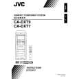 $4.99 DX-T7 JVC
Owner's Manual Complete owner's manual in digital format. The manual will be available for download as PDF file aft…
|
|
|
> |
|