Very satisfied! I was searching for several days, but nope; till I discovered your webside and there it was at a very reasonable price. Keep up the good work!
Paul
Flanders
Text excerpt from page 7 (click to view)
INSTALLATION
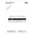
Wall drilling and bracket fixing
7.2.1
11 12a
116 116
Wall marking: � Draw a vertical line on the supporting wall up to the ceiling, or as high as practical, at the centre of the area in which the hood will be installed. � Draw a horizontal line at 650 mm above the hob. � Place bracket 7.2.1 on the wall as shown about 1-2 mm from the ceiling or upper limit aligning the centre (notch) with the vertical reference line. � Mark the wall at the centres of the holes in the bracket. � Place bracket 7.2.1 on the wall as shown at X mm below the first bracket (X = height of the upper chimney section supplied), aligning the centre (notch) with the vertical line. � Mark the wall at the centres of the holes in the bracket. � Mark a reference point as indicated at 116 mm from the vertical reference line and 306 mm above the horizontal reference line. � Repeat this operation on the other side. � Drill ø 8 mm holes at all the centre points marked. � Insert the wall plugs 11 in the holes. � Fix the lower bracket 7.2.1 using the 12a screws (4,2 x 44,4) supplied. � Fix the upper bracket 7.2.1 and the air outlet connection support 7.3 together using the 2 screws 12a (4,2 x 44,4) supplied. � Insert the two screws 12a (4,2 x 44,4) supplied in the hood body fixing holes, leaving a gap of 56 mm between the wall and the head of the screw.