|
There are currently no product reviews.
 ;
I purchased a copy of my old JVC VCR Service manual from Owner-Manuals.com
The copy was complete and valuable to me.
I was able to fix my VCR - it had a bad belt.
I am glad I found Owner-Manuals.com
Great Price. Thanks
;
Great service! I got manual to my sony receiver for very reasonoble price.
;
Good service, well organized. Cheap, and the service manual was as expected. A valuable service for those of us wanting to keep the old junk going!
;
The manual arrived very quickly and had all the information I needed - Very satisfied with this seller. - Thanks -
;
Good quality, the manual help me to repair the echo/reverb section
13. ER-A8MR
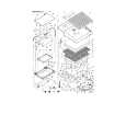
* When installing the ER-A8MR, the ER-A7RS must be also installed. 1) Remove the rear cover and rear display. 2) Install the ER-A7RS. 3) Fix the MCR angle to the lower cabinet with two screw 1. 4) Attach the accessory holder A of the ER-A7RS to the lower cabinet. 5) Fix the MCR cable of the ER-A8MR with the holder. 6) Connect the MCR cable 2 to the ER-A7RS. 7) Be sure to pass the MCR cable along the back of the lower cabinet. 8) Install the rear display and the rear cover.
4) Fix the drawer cable with pin 3, and tighten the screw on the back of the lower cabinet. * Section A in the lower cabinet (between two projections on the lower cabinet) can be opened to make a hole with the screw. * When fixing pin 3, use the cable holder fixing screw (Parts code: XHPSC30908000) (accessory of the ER03DW/04DW/05DW).
1
2
1 A Holder (LHLDW6821BHZZ)
3
2
2
3
Fig. 12
A
14. ER-03DW/04DW/05DW
Fig. 14
ER-A03DW/04DW/05DW connection
5) Fix the gnd-wire 5 from ER-03DW/04DW/05DW with a screw on the option angle.
Fig. 13 1) Remove the rear cover and rear display. 2) Connect the drawer cable 1 to the drawer connector 2 on the main PWB. 3) Remove pin 3 attached to the lower cabinet.
5
GND-wire from ER-03DW/04DW/05DW
Fig. 15
�6�
 $4.99 ER-A750 SHARP
Parts Catalog Parts Catalog only. It's available in PDF format. Useful, if Your equipment is broken and You need t…
|