|
|
|
Categories
|
|
Information
|
|
Featured Product
|
|
|
 |
|
|
There are currently no product reviews.
 ;
I was at first dubious about payiong for downloaded manuals but having done so, I was extremely impressed with quality of the two manual I ordered, well worth the small price I paid.
I would highly recommend these to my friends.
;
reasonable price for the schematic - the service is perfect, all as expected and pointed by instructions - good scan of the original plans - thank you!
;
Manual was just as described!!! I odered it and in less than a day was able to download it and the text was clear and pages were all complete just as the original manual was. Purcashed this for a friend and they were more than happy. Perfect all around!
 ;
Excellent service and prompt delivery. But it's not a manual - only 4 pages wiring diagrams.
Thanks.
;
The manual I purchased was exactly what I needed to repair my Toshica television. The manual contained schematics and troubleshooting information that was very helpful.
FU-21SE-S
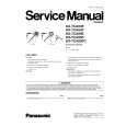
How to assemble the FERRITE CORE
(1) At first , pass the AC cord ass'y through the hole of the back panel. (2) By passing three times the connector side of AC cord ass'y through the hole of the ferrite core, make two circles near the cord bushing .
AC CORD ASS'Y
3. Removing the display PWB CAUTION The LED guide cannot be removed from the display PWB. (Because of the LED for cluster lamp.)
LED GUIDE LED (CLUSTER LAMP)
FERRITE CORE
DISPLAY PWB
(3) Pass the two circles to the boss .
BOSS
CONNECTOR D
(1) Remove the fixing screws (5 pcs.), pull out the connectors D and G (on the relay PWB) to take out the display PWB.
SCREWS DISPLAY PWB
(4) Insert the AC cord angle to the cord bushing , tighten the AC cord ass'y to the casing with the screw. 2. Removing the switch PWB (1) Pull out the connector (CN-E) of the switch PWB and remove the screws (2 pcs.). Then, take the switch PWB out of the switch PWB guide. CAUTION When taking out the switch PWB, be sure not to lose the button and the switch spring.
SWITCH PWB CONNECTOR (CN-E) SWITCH PWB GUIDE CONNECTOR D CONNECTOR G
4. Removing the power supply PWB (1) Remove the display PWB and pull out the connector (CN-D). (2) Remove the top PWB box. (3) Pull out the connector (CN-A/CN-B/CN-C/CN-F) on the power supply PWB to remove the PWB.
BACK PANEL SWITCH PWB
BUTTON SWITCH SPRING
SWITCH PWB GUIDE
5. Removing the relay PWB (1) Remove the connectors G and H. (2) Hold the head of the spacer A and take the relay PWB out of it.
CONNECTOR H
SPACER A
SWITCH PWB
CONNECTOR G
14
|
|
|
> |
|