|
|
|
Categories
|
|
Information
|
|
Featured Product
|
|
|
 |
|
|
There are currently no product reviews.
 ;
This was a hard to find manual. When I did find it , some sites wanted way too much for the file.
Owner-manual .com had it for a really reasonable price. Not only that but it was sent very quickly and was a quality scanned document, unlike some others I purchased from a different site.
Good job guys!!
Larry
;
Fast and courteous service. Product delivered as described. Thank you.
;
Last week I bought a second hand Panasonic AG-7500 SVHS Hi-Fi Video Cassette Recorder. It is a professional machine with many video and audio options. I feared it would be a huge quest to find a manual. I was delighted when I found owner-manuals.com. After payment I received the file to download the next day already. The quality is great. I am very happy. Thanks!
;
The owner's manual/operating instructions that I purchased was the original factory document and it was in at least three and maybe more languages. I no longer have it because I sold the tape recorder and included the owner's manual/operating instructions and a service/repair manual that I bought on ebay for the new owner.
;
This manual is very useful. Because pioneer sx-q180 is unhandy to use without manual.
SECTION 3 MECHANICAL ADJUSTMENTS
Replacing the Thermal Head
1) Before replacing the head, print the stair-step pattern with the old head (faulty head).
Note 1: Only when the head is not entirely damaged with black or white lines. Note 2: To reproduce the stair-step pattern, refer to �Adjusting Method 1� in �4. Electrical Adjustments�.
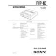
6) Remove the two screws 8 (PSW2.6 � 8) and remove the thermal head 9 from the heat sink 0. (Refer to Fig. 2)
Note: Do not remove the screw !� fixing the heat sink 0 and head arm !¡.
7) Replace the thermal head 9.
Note: Make sure that the silicon grease (white) does not stick onto the printing screen of the thermal head. If it does, remove with alcohol.
2) Remove the upper cabinet. (Refer to �2. Disassembly�.) 3) Remove the flat cables 1 (POHE13) and 2 (ADHE13) from the thermal head. (Refer to Fig. 1) 4) Remove the two screws 3 (BVTT2.6 � 6) and remove the harnesses 4 and fan holder 5. (Refer to Fig. 1) 5) Remove screw 6, (PS2.6 � 4) and remove the ribbon guide 7. (Refer to Fig. 2)
8) Assemble in the reverse order of steps 2) to 6). 9) Perform �Head Voltage Adjustment� of �4. Electrical Adjustments� (Page 4-3).
5 fan holder
3 two screws
(BVTT2.6 � 6)
7 ribbon guide 6 screw (PS2.6 � 4)
4 harness
!� two screws Note: Do not remove the screw. 8 two screws (PSW2.6 � 8)
0 heat sink
1 flat cable (POHE13)
2 flat cable (ADHE13)
9 thermal head
!¡ head arm
Fig. 2
Fig. 1
3-1 E
 $4.99 FVP1E SONY
Service Manual Complete service manual in digital format (PDF File). Service manuals usually contains circuit diagr…
|
|
|
> |
|