|
|
|
Categories
|
|
Information
|
|
Featured Product
|
|
|
 |
|
|
There are currently no product reviews.
 ;
This was an excellent source of detailed assembly information on a device which is at least 12 years old. A very lucky find, coupled with great service.
;
Excellent Service Manual and best price on the Internet. This Service Manual covers everything you could ever need including full circuit schematics, component layout diagrams, stripdown procedure and full parts list/breakdown. I needed this to carry out a modification to one of these headunits and this manual covered everything I needed. Fast delivery, processed within a few hours.
 ;
Thought I would never find a copy of the Technics SX-EN2 Service Manual until I found Owner-Manuals.com. Price was very fair and I received the download promptly. While a photocopy, it is quite readable and includes all the pertinent information and diagrams. Thank you Owner-Manuals!
;
I really like this manual and it's reliable.I found and bought easly.thank you.
;
Thank you very much. the Instruction corresponds to my expectations. Sent it in time. I don't regret that paid money.
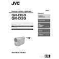
2.1.6 CHECKUP AND ADJUSTMENT OF MECHANISM PHASE
[24]MODE GEAR
Align the MODE GEAR with the Main Deck Assembly hole. Note: The MODE GEAR may be displaced during the mechanism operation, however it can be checked fr om the rear and realigned during manual assembly.
[27]ROTARY ENCODER
Mount the ROT ARY ENCODER by aligning its mark ( and the mark ( ) of the Main Deck Assembly. Note: Be careful when handling the FPC during mounting. )
[34]REEL GEAR 1
Align the REEL GEAR 1 with the Main Deck Assembly hole. Note: The REEL GEAR 1 may be displaced during mechanism operation, however this can be checked fr om the rear and realigned during manual assembly.
[29] MAIN CAM ASSY/[30]SLIDE ARM ASSY
When mounting the SLIDE ARM ASSY align it with the Main Deck Assembly and MAIN CAM ASSY holes. Note: During the mounting pr ocedure, make sure that the[32] SUB CAM ASSY is in the correct mounting position.
[32] SUB CAM ASSY/[33] CONTROL ARM ASSY
Mount the SUB CAM ASSY hole to align with the CONTROL ARM ASSY and Main Deck Assembly holes and then tighten them all together with a screw. Note: When mounting it, make sure that the[29]MAIN CAM ASSY is in the correct mounting position.
Fig.2-1-25
2-14 (No.86700)
 $4.99 GR-D30AS JVC
Owner's Manual Complete owner's manual in digital format. The manual will be available for download as PDF file aft…
|
|
|
> |
|