|
|
|
Categories
|
|
Information
|
|
Featured Product
|
|
|
 |
|
|
There are currently no product reviews.
 ;
I purchased the unit from a private party and the original owners manual was not available. Having the ability to download it was extremely helpful and clarified operating the equipment immensely. This is a complicated unit and without the manual I would not have been able to maximize it's potential. Thank you.
;
Being a user of older radios of many kinds, preferring them over more modern rigs, this manual was invaluable in the programming of my two. I now know for certain what the assorted buttons functions are, and am very grateful to have found this excellent site. Many thanks for your assistance, Tony.
 ;
Clear and easy to read. All details as expected. Price acceptable , and quick delivery.
;
Quick response and exactly what I was looking for and at a great fair price!
;
5 star quality on these downloadable manuals. Easy to read and all the information is there. A must when doing a custom install or needing to service your precious old school electronics.
SERVICE NOTE
1. POWER SUPPLY DURING REPAIRS
In this unit, about 5 seconds after power is supplied (8.4V) to the battery terminal using the service power cord (J-6082-223-A), the power is shut off so that the unit cannot operate. This following two methods are available to prevent this. Take note of which to use during repairs.
Battery terminal �
Battery sig terminal
Method 1.
Connect the servicing remote commander RM-95 (J-6082-053-B) to the LANC jack, and set the remote commander switch to the �ADJ� side.
Battery switch
Method 2.
Press the following battery switch using adhesive tape, etc.
Battery terminal �
2.
HOW TO TAKE A CASSETTE OUT WHEN THE MAIN POWER CANNOT BE TURNED ON (FORCED EJECTED)
Procedure: 1. Remove the cassette lid referring to the section �2. DISASSEMBLY, 2-1�. 2. Remove the operation switch block (FK-71 board) referring to the section �2. DISASSEMBLY, 2-5�. 3. Remove the CB-61 board referring to section �2. DISASSEMBLY, 2-4�, and remove the FP-586 flexible board from CN3140 (4P) on the RJ-77 board. 4. Apply +4.5 V from the regulated power supply to the loading motor terminal as shown below and remove the cassette. CAUTION: Be careful not contact with the lid frame assembly when applying +4.5 V.
Control switch block
Regulated power supply
4.5V GND
Lid frame assembly Loading motor
3.
WARNING INDICATORS
If the CAUTION lamp flashes, but no indicators appear on the LCD screen or on the monitor TV screen, it means that an error occurs either in the fan motor or in the fan motor drive circuit. Refer to the schematic diagram on page 4-43 for repair.
�5�
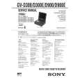 $4.99 GVD900 SONY
Service Manual Complete service manual in digital format (PDF File). Service manuals usually contains circuit diagr…
|
|
|
> |
|