|
|
|
Categories
|
|
Information
|
|
Featured Product
|
|
|
 |
|
|
There are currently no product reviews.
 ;
complete part-lists and pcb layout, schematic diagram is good enlargable,
;
Excellent, fast delivery, excellent product. Good luck!
;
This manual is for the usa model only. But it is clear
, accurate and comprehensive, including board layouts and schematics.
I found it extremely useful for my mitsubishi dp-86da, but the same diagram would also work for the realistic lab5000 and hi fi 80. Thanks.
;
Great to have extra resources for Service Manuals, Now days you can really not trouble shoot efficiently without one , Wayne at IRIONS TV & ELECTRONICS REPAIR Clearwater , Fl. 33755 727-446-7955
 ;
For five bucks you can barely buy a hamburger. Or for the same five bucks you can buy a service manual. Much more useful. (and better for your health, depending on where you buy your hamburgers).
Yes, there are free manual sites out there, but if they don't have what you want, you have to pay.
And five bucks isn't much. Not for full specs, schematics and adjustment and parts replacement procedures.
My only criticism is that grayscale illustrations aren't well rendered, but I've seen worse.
Schematics and text are clear.
I'll be happy to purchase from here again.
Mike
[email protected]
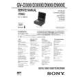
SERVICE NOTE
1. POWER SUPPLY DURING REPAIRS
In this unit, about 5 seconds after power is supplied (8.4V) to the battery terminal using the service power cord (J-6082-223-A), the power is shut off so that the unit cannot operate. This following two methods are available to prevent this. Take note of which to use during repairs.
Battery terminal �
Battery sig terminal
Method 1.
Connect the servicing remote commander RM-95 (J-6082-053-B) to the LANC jack, and set the remote commander switch to the �ADJ� side.
Battery switch
Method 2.
Press the following battery switch using adhesive tape, etc.
Battery terminal �
2.
HOW TO TAKE A CASSETTE OUT WHEN THE MAIN POWER CANNOT BE TURNED ON (FORCED EJECTED)
Procedure: 1. Remove the cassette lid referring to the section �2. DISASSEMBLY, 2-1�. 2. Remove the operation switch block (FK-71 board) referring to the section �2. DISASSEMBLY, 2-5�. 3. Remove the CB-61 board referring to section �2. DISASSEMBLY, 2-4�, and remove the FP-586 flexible board from CN3140 (4P) on the RJ-77 board. 4. Apply +4.5 V from the regulated power supply to the loading motor terminal as shown below and remove the cassette. CAUTION: Be careful not contact with the lid frame assembly when applying +4.5 V.
Control switch block
Regulated power supply
4.5V GND
Lid frame assembly Loading motor
3.
WARNING INDICATORS
If the CAUTION lamp flashes, but no indicators appear on the LCD screen or on the monitor TV screen, it means that an error occurs either in the fan motor or in the fan motor drive circuit. Refer to the schematic diagram on page 4-43 for repair.
�5�
 $4.99 GV-D900 SONY
Owner's Manual Complete owner's manual in digital format. The manual will be available for download as PDF file aft…
|
|
|
> |
|