|
|
|
Categories
|
|
Information
|
|
Featured Product
|
|
|
 |
|
|
There are currently no product reviews.
 ;
Complete manual included schematics layouts and alignment procedure, clear to read and magnify, extremely pleased with manual and owner manual . com's service
;
perfect, i am very satisfait for the réception of the sansui r-5l service manual, thank you very much
;
Thank you, this is a rare document. Few others have it, but they charge way more for a download.
Great deal (even if you have to wait a few hours to get it).
;
The purchased manual is an high quality scan of the original Philips paper-based Service Manual. I am very satisfied!
 ;
The purchased manual is an scan of the original Panasonic paper-based Service Manual. Unfortunately the contrast is not perfect, but I am satisfied anyway!
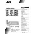
2.3.2 Checking/Adjustment of the Height and Tilt of the Audio Control Head Note: Set a temporary level of the height of the A/C head in advance to make the adjustment easier after the A/C head has been replaced. (See Fig.22-15.) (1) Connect CH-1 of the oscilloscope to AUDIO OUT and CH2 to TP4001 (CTL.P) of the main board assembly and observe the waveforms on both channels in the ALT mode. (2) Play the alignment tape MHPE and adjust it by turning the screws (1), (2) and (3) little by little until the waveform of both the audio output signal and the control pulse reach maximum. The screw (1) and screw (3) are for adjustment of tilt and screw (2) for azimuth.
(6) Then play the alignment tape MHPE-L. (7) Press the channel buttons (+, �) simultaneously during playback to enter the manual tracking mode. (This also brings the tracking to the centre.) (8) Perform the tracking operation and make sure that the FM waveform is at its maximum. (9) If it is not at maximum, loosen the temporarily tightened the screw (4) and turn the A/C head position bit to bring the audio control head to a position, around where the waveform reaches its maximum for the first time. Then tighten the screws (4) and (5).
Toward the capstan Toward the drum
Head base
Head base A/C head position bit PTU94010
Waveform output
Screw (4)
(2)
(1)
To the drum
(3) Audio control head
Screw (5) Audio control head To the capstan
Audio out
Fig. 2-3-6
TP4001 (CTL. P)
Fig. 2-3-5
MHPE played with the standard-width head
MHPE-L played with the triple-width head
2.3.3 Checking/Adjustment of the Audio Control Head Phase (X-Value) (1) Connect the oscilloscope to TP106(PB.FM) of the main board assembly and to TP111(D.FF) of the main board assembly for external sync connection. (2) Play the alignment tape MHPE and observe the FM waveforms. (3) Press the channel buttons (+, �) simultaneously during playback to enter the manual tracking mode. (This also brings tracking to the centre.) (4) Loosen screws (4) and (5) so that the A/C head position bit (PTU94010) is set as indicated in Fig.2-3-6. (5) Turn the A/C head position bit fully toward the capstan. Then turn it back gradually toward the drum and stop on the second peak point position of the FM waveform output level. Then tighten the screw (4) temporarily.
X-value adjustment point To the drum Control head position To the capstan
Maximize
Fig. 2-3-7
2-22
|
|
|
> |
|