|
|
|
Categories
|
|
Information
|
|
Featured Product
|
|
|
 |
|
|
There are currently no product reviews.
 ;
The service manual is as described and received the link to the download sooner than expected. Great service, quality product. This site is a big help in the electronics repair business.
;
Il service manual molto accurato. Rapidi nella risposta
;
Quick site processing. A complete and very useful manual with all details. Thank you!
;
Quick service response. A useful and very rare service manual with all details. I recomend this service.
;
I ordered this manual sometime in the afternoon and I received it on my e-mail the same evening.
This is a fantastically good and properly scanned copy of the original manual. All pages are of the same scale and they overlap each other. It means that you can print the manual and easily make it as a convenient paper manual.
The content of the manual is fantastic. Alignment descriptions, PCB layouts and elementary diagrams are explicit and precise. I immediately found what I was looking for. Thanks to this manual and Owner-Manuals.com my amplifier is alive again. Many thanx indded!
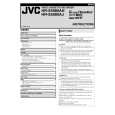
2.2.17 Take-up lever, take-up head and control plate guide (1) Remove the spring of the take-up lever from the main deck. (2) Remove the lug (A) of the take-up lever from the main deck and pull out the take-up lever and the take-up head together. (3) Remove the screw (A). (4) Align the idler arm assembly pin in the center (centre) of the R section of the control plate guide, remove the control plate guide lugs (B) and (C) from the main deck, and remove the control plate guide.
Idler arm assembly pin Lug(C) Take-up lever
Spring Sub brake Lug(A) assembly (take-up side)
Lug(B)
Lug(C)
Fig. 2-2-19a 2.2.20 Main brake assembly (take-up side), reel disk (take-up side) and main brake assembly (supply side) 1. How to remove (1) Move the main brake assembly (take-up side) in the arrow-indicated direction and remove the reel disk (takeup side). (2) Remove the spring attached to the main brake assembly. (3) Remove the lug (A) of the main brake assembly (takeup side) and pull out the lug (B) after bringing it into alignment with the main deck notch. (4) Remove the lugs (C), (D) and (E) of the main brake assembly (supply side) from the main deck and pull them off. (See Fig.2-2-20a.) (5) When installing the main brake assembly (take-up side), slide the brake lever in the direction as indicated by the arrow to prevent it from hitting the projection of the main brake assembly (take-up side). (See Fig.2-2-20b.)
Main brake assembly (supply side) Reel disk (take-up side) Main brake assembly (take-up side)
Screw(A) Take-up head
Lug(A) Lug(B)
Control plate guide
Fig. 2-2-17a 2.2.18 Capstan brake assembly
1. How to remove (1) Move the lug (A) of the capstan brake assembly in the arrow-indicated direction so that it comes into alignment with the notch of the main deck. (See Fig. 2-2-18a.) (2) Remove the lug (B) of the capstan brake assembly from the main deck and remove the capstan brake assembly.
Lug(B)
Lug(A)
Lug(B) Notch Lug(C) Lug(D) Lug(E) Spring Lug(A)
Capstan brake assembly
Fig. 2-2-20a Fig. 2-2-18a
Rotary encoder guide ( 1) Brake lever Projection of the main brake assembly (take-up side)
2.2.19 Sub brake assembly (take-up side) 1. How to remove (1) Remove the spring attached to the lid guide and sub brake assembly (take-up side). (2) Bring the lug (A) of the sub brake assembly (take-up side) into alignment with the notch of the main deck. (3) Remove the lugs (B) and (C) of the sub brake assembly (take-up side) from the main deck and remove the sub brake assembly (take-up side).
*
Note: � The parts with marked ( ) have different types of mechanisms (standard type or high-speed FF/REW type). 1 : Uses the standard type mechanism only.
*
*
Fig. 2-2-20b 2-13
|
|
|
> |
|