|
|
|
Categories
|
|
Information
|
|
Featured Product
|
|
|
 |
|
|
There are currently no product reviews.
 ;
It was very usefull, it is clear the quality is super, the price I paid is very afordable.
Generally speaking Iam very happy with this company.
;
The manual was exactly what I needed, Good quality scans too. superb.
;
I am so happy found this site as it consists of so many Manuls and easy to aquire. This onei s exactly what I wanted and much more as it has info on not only how to use the tuner but how to repair it as well. I will come here 1st before purchasing else where! Thanks owner-manual.com!
;
Top class product, I printed it out on A3 paper and it is clear and very easy to follow.
Cheaper than buying a new radio!
;
is part of the manual is very useful for repairing
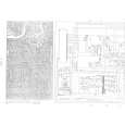
Here are circuit diagrams
if there is damage, I recommend using this part of the
a complete list of circuit boards and components
SECTION 2 MECHANISM
2.1 Before disassembling 2.1.1 Notes This model�s mechanism relates closely to the rotary encoder and system control circuit (the rotary encoder is meshed with the control cam). The system control circuit detects the mechanism condition using the rotary encoder�s phase (internal switch phase). Therefore, the parts such as the rotary encoder, control plate, loading gear and control cam need to be installed correctly in order for the mechanism to operate properly. (For the mechanism phase adjustment, refer to the installation of each part.) � For the disassembly procedure of the major parts of the main unit and notes, refer to the �section 1 disassembly�. � Before using a soldering iron, be sure to disconnect the power plug from the AC outlet. � Do not touch any of the adjustment points until a defect position is specified. � When plugging or unplugging the connector, be sure not to damage the wire. � Be sure the springs are hooked all the way around and in the correct direction. � When performing repairs, take care not to damage a catch, etc. 2.1.3 Setting the mechanism assembling mode The mechanism-assembling mode is provided with this mechanism. When disassembling and assembling, it is required to engage this mode. Set the mode by adopting the following procedures. (1) Remove the mechanism assembly using the disassembling procedure. (2) Turn gear (a) of the loading motor manually to set the mechanism assembly to the eject end mode. Make sure that the main deck is connected to the guide hole (a) of the drive lever and the seal (a) of the main deck is connected to the mark �E� of the control plate. This condition is called the mechanism-assembling mode.
Seal (a)
Guide hole (a)
�E� mark CONTROL PLATE DRIVE LEVER
<Example>
OK
(
NG not hooked all the way around
)
Fig. 2-1-1a
2.1.2 Mechanism operation check When the mechanism is operated without a cassette loaded, operate the mechanism in the mechanism service mode. (Refer to the "section 1 disassembly".)
LOADING MOTOR
Gear (a)
Unloading
Loading
Fig. 2-1-3a
2-1
|
|
|
> |
|