|
|
|
Categories
|
|
Information
|
|
Featured Product
|
|
|
 |
|
|
There are currently no product reviews.
 ;
Very usefully, I could find the trouble clearly with that manual.
;
Bon produit. Permet de corriger les couleurs et de redonnez un petit coup de jeune à vos vieilles vidéos. On regrettera juste le manque d'une prise s-vidéo.
 ;
Quality scan of the actual service manual, just what I was looking for.
;
Straightforward ordering process. Service manual scan was clear & easy to read. Very comprehensive instructions for alignment. Excellent, thank you.
;
Fast, clear and useful. Important for me: the manual is in German.
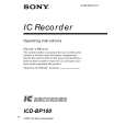
ICD-BP100/BP120
US Model
ICD-BP100/BP120
SERVICE MANUAL
Ver 1.1 2002. 07
IC 101 107 IC 103
Canadian Model AEP Model UK Model E Model
ICD-BP100
Tourist Model
ICD-BP100/BP120
SUPPLEMENT-1
Subject : 1. Cautions of FLASH MEMORY (IC706) exchange
(SPM-02033)
[Precaution when the flash memory (IC706) is replaced] When the flash memory (IC706) is replaced, be sure to perform the BAD BLOCK check* and writing of the model code. If they are not completed, the unit will not operate normally. * BAD BLOCK check is to check the flash ROM memory area (the BAD BLOCK area) where data cannot be guaranteed. The resultant information of this check is stored in the TOC-AREA so that the BAD BLOCK area should not be used. BAD BLOCK Check Procedure 1. When the power is turned on after the flash memory (IC706) is replaced, the BAD BLOCK check starts automatically and the OPR (D703) lights in orange. 2. In about 4 to 5 minutes after start of the check, the OPR (D703) changes the color to green indicating that the check is completed.
Model Code Writing Procedure 1. After the BAD BLOCK check is complete, press the MENU switch and the STOP switch at the same time. While keeping pressing the MENU and the STOP switches simultaneously, turn on the HOLD switch to start the test mode. 2. After the unit enters the test mode, connect TP703 of the MAIN board and TP512 of the F-SW board with a jumper. Then the unit enters the Model Code Writing mode. 3. When the unit is ICD-BP100, press the > switch. When the unit is ICD-BP120, press the zREC switch. 4. When the OPR (D703) lights in red, it indicates that the writing is terminated with success. If the OPR (D703) lights in orange, it indicates that the writing has failed with error. Make another attempt of writing the model code from the beginning. 5. Remove the jumper between TP703 of the MAIN board and TP512 of the F-SW board.
MAIN BOARD (SIDE A)
TP703
F-SW BOARD (SIDE A)
A-B REPEAT /PRIORITY INDEX/ BOOKMARK
TP512
J101
MIC (PLUG IN POWER)
DISPLAY
BP100
ERASE
IC 102
I
J102
EAR
1
24
IC 108
OPR
12
13
IC 105
IC 507
STOP MENU
|
|
|
> |
|