|
|
|
Categories
|
|
Information
|
|
Featured Product
|
|
|
 |
|
|
There are currently no product reviews.
 ;
I purchased a copy of my old JVC VCR Service manual from Owner-Manuals.com
The copy was complete and valuable to me.
I was able to fix my VCR - it had a bad belt.
I am glad I found Owner-Manuals.com
Great Price. Thanks
;
Great service! I got manual to my sony receiver for very reasonoble price.
;
Good service, well organized. Cheap, and the service manual was as expected. A valuable service for those of us wanting to keep the old junk going!
;
The manual arrived very quickly and had all the information I needed - Very satisfied with this seller. - Thanks -
;
Good quality, the manual help me to repair the echo/reverb section
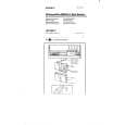
SECTION 3 ELECTRICAL ADJUSTMENTS
FM section Setting BAND switch : FM
FM RF signal generator 0.01µF Set 22.5 kHz frequency deviation by 400 Hz signal Output level : as low as possible
0 dB=1µV
� This adjustment should be executed after MW band adjustment is completed because the LW and SW bands use the BAR ANT and CV1 in common with the MW band. Therefore, if MW band is adjusted, the LW and SW bands must also be readjusted. FM FREQUENCY COVERAGE ADJUSTMENT Adjust for a maximum reading on Level meter. L7 CT1-4 87.3MHz (75MHz) 108.3MHz (109.5MHz)
telescopic antenna input
FM TRACKING ADJUSTMENT Adjust for a maximum reading on Level meter. L6 87.3MHz (75MHz) CT1-3 108.3MHz (109.5MHz)
MW/LW section Setting BAND switch : MW/LW
AM RF signal generator Put the lead-wire antenna close to the set. 30% amplitude modulation by 400 Hz signal Output level : as low as possible
MW FREQUENCY COVERAGE ADJUSTMENT Adjust for a maximum reading on Level meter. L4 520kHz CT1-2 1,650kHz
MW TRACKING ADJUSTMENT Adjust for a maximum reading on Level meter. L1 600kHz CT1-1 1,400kHz
SW section Setting BAND switch : SW1 � SW9
AM RF signal generator 8pF Set 30 % amplitude modulation by 400 Hz signal Output level : as low as possible
AM IF ADJUSTMENT Adjust for a maximum reading on Level meter. T1 455kHz LW FREQUENCY COVERAGE ADJUSTMENT Adjust for a maximum reading on Level meter. L5 CT3 137kHz 295kHz LW TRACKING ADJUSTMENT Adjust for a maximum reading on Level meter. L2 155kHz CT2 260kHz
telescopic antenna input
Level meter 32� Set
Headphones jack (J1)
� Preparation for SW band adjustment After making sure that the MW band adjustment has completed, set the pointer to the center of character of 6.0, 7.2, 11.8 or 21.6MHz which is reference position of dial character, and fix the CV1 at this position. ( ) : Tourist model
� Repeat the procedures in each adjustment several times, and the frequency coverage and tracking adjustments should be finally done by the trimmer capacitors.
�6�
|
|
|
> |
|