|
|
|
Categories
|
|
Information
|
|
Featured Product
|
|
|
 |
|
|
There are currently no product reviews.
 ;
Perfect copy of a necessary document and my Sonic Modulator is repaired!
;
Excellent replacement for original Manual. Worth every cent ! I am totally satisfied!
;
Only in this place I could find this manual. Very complete and very clear. PDF is a very good quality and easily read. Thank you. I was very useful.
Videoson & ltd.
;
It is great, it saves money and paper. It helps me to save room and recources.
;
manual service is ok , resolve the problems
manual service is ok , resolve the problems
manual service is ok , resolve the problems
manual service is ok , resolve the problems
manual service is ok , resolve the problems
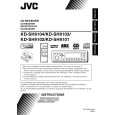
3.1.6 Removing the main board (See Figs.12 to 16) � Prior to performing the following procedures, remove the top chassis and motor assembly. (1) Disconnect the flexible wires from the connectors CN703 and CN991 on the main board respectively. (See Fig.12.) (2) Move the front bracket backward until it stops. (3) Remove the four screws L attaching the arm brackets (L) and (R). Move the arm brackets (L) and (R) from the rod gear. (See Fig.12.) (4) Remove the rod gear. (5) Remove the screw M attaching the rear panel to the bottom cover from the back side of the main body. (See Fig.14.) (6) Remove the three screws N attaching the main board and move the main board backwards to release the two joints c. (The main board will be removed with the rear panel and rear heat sink) (See Figs.12 and 15.) (7) Remove the screw P and Q attaching the rear heat sink. (See Fig.16.) (8) Remove the three screws R and screw S attaching the rear panel, then remove the main board. (See Fig.16.)
Rear panel
Bottom cover
M
Fig.14
Joint c Joint c Main board
N
Main board
N
Arm brackets (L) Arm brackets (R)
Fig.15
L
L R P
CN703
CN991
Fig.12
M
Rod gear
Arm brackets (L) Rear panel Arm brackets (R)
S
Q
Rear heat sink
Fig.16
Main board
Rod gear
Fig.13 1-10 (No.49841B)
|
|
|
> |
|