|
|
|
Categories
|
|
Information
|
|
Featured Product
|
|
|
 |
|
|
There are currently no product reviews.
 ;
It was easy to order and received exactly what I needed. Only complaint would be the 24 hours you have to wait.
 ;
Manual was delivered in a timely manner and was all in English as advertised. The manuals I received when we moved into our flat were in German, Italian, and French. Having never used a steamer before, and not speaking/reading German very well, I needed an English Manual. this was a huge help.
;
Great Manual. This manual is available no where else. It was exactly what I was looking for. Only in German.
;
This GRUNDIG UV5A Owner Manual is not only an instruction manual but a total functional circuit description of the Multimeter and includes circuit diagram at the end pages. It is very helpful for repairing and calibrating the instrument. It is written in two languages English and German for international support. It was very easy to repair my unit with this document. Regards, Regis Pauly, Electrical Engineer.
;
The owner's manual was evetything I thought it would be. I was able to print it out using both sides of the paper in quick order, saving me a search online for a used one.
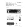
Connecting Cables to Terminals
Connecting the ISO Connector (see p.24) The pin arrangement for the ISO connectors depends on the type of vehicle you drive. Make sure to make the proper connections to prevent damage to the unit. The default connection for the wiring harness is described in 1 below. If the ISO connector pins are set as described in 2 or 3, make the connection as illustrated. 1 (Default setting) The A-7 pin (red) of the vehicle's ISO connector is linked with the ignition, and the A-4 pin (yellow) is connected to the constant power supply. Unit Vehicle Ignition cable (Red) A�7 Pin (Red) Battery cable (Yellow) A�4 Pin (Yellow)
2WARNING
Installation s Installation
Firewall or metal support
Accessory3
Bend the tabs of the mounting sleeve with Self-tapping screw (commercially available)
NOTE
2 The A-7 pin (red) of the vehicle's ISO connector is connected to the constant power supply, and the A-4 pin (yellow) is linked to the ignition. Unit Vehicle Ignition cable (Red) A�7 Pin (Red) Battery cable (Yellow) A�4 Pin (Yellow)
Metal mounting strap (commercially available)
a screwdriver or similar utensil and attach it in place.
Make sure that the unit is installed securely in place. If the unit is unstable, it may malfunction (eg, the sound may skip).
3 The A-4 pin (yellow) of the vehicle's ISO connector is not connected to anything, while the A-7 pin (red) is connected to the constant power supply (or both the A-7 (red) and A-4 (yellow) pins are connected to the constant power supply). Unit Vehicle Ignition cable (Red) A�7 Pin (Red) Battery cable (Yellow)
NOTE
A�4 Pin (Yellow)
When the connection is made as in 3 above, the unit's power will not be linked to the ignition key. For that reason, always make sure to turn off the unit's power when the ignition is turned off. To link the unit's power to the ignition, connect the ignition cable (ACC...red) to a power source that can be turned on and off with the ignition key.
� 25 �
|
|
|
> |
|