|
|
|
Categories
|
|
Information
|
|
Featured Product
|
|
|
 |
|
|
There are currently no product reviews.
 ;
Once again owner-manual.com has saved the day for me, and come through with the manual I need. I looked other places too, and couldn't find it anywhere. Thank You owner-manual.com!!! You're the BEST!
;
very good quality that can be magnified several times, and it remains readable.
For sure I will return next time the need for a service manual arise.
;
The service manual is really great - thanks to it I was able to install the laser unit and thus "save" my CD-player, which seemed to be impossible before I had the manual.
;
Downloaded the Service manual OK of the Technics Piano and have now repaired it and its going fine. Excellant; thank you for the fine servce. A.M
 ;
This site is working fine! Did buy a manual for SX-EX25L and after a while I could download it and fix the problem. Nice and easy!
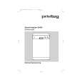
KS-F363R/KS-F360R
<Cassette mechanism assembly>
Prior to performing the following procedures, remove the head amplifier board, the relay board and the mechanism bracket.
C
FF / REW lever assembly Joint c
Removing the direction switch board (See Fig.1)
1. Unsolder the three wires a on the direction switch board. 2. Remove the one screw A switch board. attaching the direction
Joint e
Joint d
A B
Joint b
Removing the FF / REW lever assembly (See Fig.1)
1. Remove the screw B attaching the FF / REW lever assembly on the back of the cassette mechanism assembly. 2. Remove the screw C on the upper side of the FF / REW lever assembly. 3. Lift and pull forward the FF / REW lever assembly to disengage the joints b, c, d and e.
Soldering a Direction switch board
Fig.1
Reattaching the FF / REW lever assembly (See Fig.1)
1. Reattach the FF / REW lever assembly to the joint c on the back of the chassis. 2. Reattach the pinch-roller shaft e, the change lever d and the return link e to the chassis.
1-7
|
|
|
> |
|