|
|
|
Categories
|
|
Information
|
|
Featured Product
|
|
|
 |
|
|
There are currently no product reviews.
 ;
Response is a little slow- I had to wait 12 hours to receive download link but it says that it may take up to 24hrs.
Manual is old and was not produced in PDF- scanned copy is exellent.
Overall- value for money- I recommend
 ;
Excellent quality and quickly delivered manuals at a fair price. Great care is taken in the reproduction process. Even photographs and highly detailed drawings are as clear as in the original. That cannot be said for some freelance manual copies I have obtained from the web. If you have exhausted your internet search of technical manuals, try Owner-Manuals.com. If they do not have it, I do not think it exists. Perhaps, if requested, they may be able to find it. Their resources are certainly greater than most. Shopping here certainly beats waiting for months or years for the manual you seek to appear in an internet auction or garage sale.
;
Very detailed product, also it is a scanning from original, very useful if you have to service this type of amplifier ! Very good product, very hard to find!
;
the Manual was made available as promised, the scans were excellent..Good Work !!!
;
It's complete and helpful manual with good quality of scan. Thanks very much.
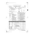
KS-LX200R
Removing the main board assembly (See Fig.6 to 8)
Prior to performing the following procedure, remove the top chassis. 1. Remove the screw S attaching the bracket (L). 2. Disconnect the flexible harness from connector CN701, the card wire from CN702 on the main board and the harness from CN503 and CN504 respectively. 3. Remove the three screws H attaching the main board assembly to the bottom cover on the upper side of the body. 4. Remove the screw I attaching the rear panel and the bottom cover on the back of the body. Move the main board in the direction of the arrow and release the two joints a. (At this point, the main board can be removed with the rear panel and the rear heat sink.) 5. Remove the screw J and the two screws K attaching the rear heat sink on the back of the body. 6. Remove the two screws L and the screw M attaching the rear panel. Now, the main board assembly will be removed. ATTENTION: When reassembling, correctly engage the switch S561 and S562 on the main board with the part e of the operation assembly (Refer to Fig.7, 18 and 19).
Main board S652 S651 CN503 Bracket (L) CN701 Main board assembly CN504
H S H Joint a
Joint a CN702 Front panel assembly
H
Fig.6
e
Fig.7
M L L
Rear heat sink
J
Rear panel
K
I
Fig.8
1-4
|
|
|
> |
|