|
|
|
Categories
|
|
Information
|
|
Featured Product
|
|
|
 |
|
|
There are currently no product reviews.
 ;
Very good scanning quality. All schematics are very legible. Worth every cent !
;
Excellent quality, very quick download turnaround, will definately use again.
 ;
This is a awesome quality scan of the original Service Manual for Technics 8099.
Contains the circuit diagram, PCB layout, adjust/tune instructions as well.
Since this is my first buy here, i'm really glad! This site do works as intended/described, it's definitely not scam!
Мои рекомендации! Все мануалы настоящие!
;
Good Quality of the File.
You get the normal manual is incudet.
;
Very nice and real Service Manual, I didn't thought it actually exist in the real world at all.
KV-J14PF1S
SECTION 3 SET-UP ADJUSTMENTS
� � The following adjustments should be made when a complete realignment is required or a new picture tube is installed. These adjustments should be performed with rated power supply voltage unless otherwise noted. Perform the adjustments in the following order: 1. Beam Landing 2. Convergence 3. Focus 4. White Balance Note : Test Equipment Required: 1. Color-bar/Pattern Generator 2. Degausser 3. Oscilloscope
RM-869E
Controls and switch should be set as follows unless otherwise noted: PICTURE control ........................................................... normal BRIGHTNESS control ................................................... normal
.................................................................................................................................................................................................................................
Preparation : � In order to reduce the influence of geomagnetism on the set's � picture tube, face it east or west. Switch on the power and degauss with the degausser.
Purity control
3-1. BEAM LANDING
1. Input a white signal with the pattern generator. Contrast normal Brightness
}
Fig. 3-2
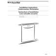
2. Set the pattern generator raster signal to green. 3. Move the deflection yoke to the rear and adjust with the purity control so that the green is at the center and the blue and the red take up equally sized areas on each side. (See Figures 3-1 through 3-3.) 4. Move the deflection yoke forward and adjust so that entire screen is green. (See Figure 3-1.) 5. Switch the raster signal to blue, then to red and verify the condition. 6. When the position of the deflection yoke has been decided, fasten the deflection yoke with the screws. 7. If the beam does not land correctly in all the corners, use a magnet to adjust it. (See Figure 3-4.)
b a
BLUE RED
GREEN
Fig. 3-3
Purity control corrects this area. Disk magnets or rotatable disk magnets correct these areas (a-d).
c
d
Deflection yoke positioning corrects these areas. b
c
Fig. 3-1
a
d
Fig. 3-4
� 13 �
|
|
|
> |
|