|
|
|
Categories
|
|
Information
|
|
Featured Product
|
|
|
 |
|
|
There are currently no product reviews.
 ;
OK?..manual is complet and helpfull... for repairing such a old and rare boombox like JVC PCM it is necessary...
;
Super Anleitung. Ordentliche Auflösung. Das ganze noch in Deutsch wäre zu schön. Alle Datenblätter sind sauber Kopiert und alle Leitungswege sind sauber ausgeführt
;
Thanks God for the internet and thanks for the service like this - proffessional solution on time.
;
About the service it's very fast and reliable. About the manual the quality is high enough to read even the tiniest details on the wiring diagrams so you can't ask much more than that, let it alone for a manual of a product from 20 years ago. Thank you, very satisfied.
;
The downloaded quality was as good as the orignial
LC-30HV4U LC-30HV4D
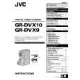
7. Remove the system/control terminal retaining: 7-1. Remove the four hex head screws securing the terminals of the system and control cables (white). 7-2. Remove the two screws securing the terminal of the system cable (gray). 7-3. Remove the two rear chassis retaining screws. 8. Remove the PC I/F and SR units: 8-1. Remove the six PC I/F top shield retaining screws and remove the shield. 8-2. Remove the six PC I/F unit retaining screws and remove the unit. 8-3. Remove the two PC I/F bottom angle retaining screws and remove the angle. 8-4. Remove the two SR unit retaining screws and remove the SR unit. 9. Remove the rear chassis. 9-1. Remove the three tuner nuts. 9-2. Remove the 10 rear cabinet retaining screws and remove the rear cabinet. 10. Remove the three power unit retaining screws and remove the power unit.
8-1
8-2 PC I/F Top Shield
Rear cabinet 9-2 9-2 9-2 9-1
8-3 PC I/F unit
PC I/F Bottom Angle
SR unit 8-4
7-1 7-2 7-3
10
Power unit
15
|
|
|
> |
|