|
There are currently no product reviews.
 ;
Please tell us what you think and share your opinions with others. Be sure to focus your comments on the product. You will receive $2.50 of store credit for Your review.
;
hat alles sehr gut geklappt. Das Servicemaual ist gut zu verwenden. Die Pläne und Schrift
ist klar und leserlich. Außerdem preiswert. Grüße an alle Hifi-Bastler
;
I got the manual quickly after the payment was transfered (1 day). The manual was exactly what i needed and the updates via e-mail were great. Thanx!
;
I've looked for this manual all over that internet, you guys had it and to a good price. A++++
;
I've looked some time for this manual, you guys had it and to a good price. A++++
4-2
LC6231/LC7181
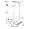
5. Remove the 6 screws �F� holding the top shield (Fig. 5). Then remove the 3 screws �G� and the 2 screws �H� (Fig. 6). Now the top shield can be removed. 2. Remove screw �K� and connectors �L� (Fig. 8). Nor the DRB (Drive Boards) can be removed.
DRB Board
F F F
F
F
F
CL 266450004_049.eps 240402
K
L
CL 266450004_052.eps 240402
Fig. 5
Fig. 8
H
H
3.
Remove screw �L� (Fig. 9). Now the bottom shield can be removed.
L
G
G
G
CL 266450004_050.eps 24402
Fig. 6 4.2 Panel removal and service position 1.
Bottom Shield
Remove screw �I� and connectors �J� (Fig. 7). Now the SSB (Small Signal Board) can be removed. The SSB is plugged onto the DRB (Drive Board).
DRB Board
Fig. 9
CL 266450004_053.eps 240402
J
J J
I
SSB Board
CL 266450004_051.eps 240402
Fig. 7
|