|
|
|
Categories
|
|
Information
|
|
Featured Product
|
|
|
 |
|
|
There are currently no product reviews.
 ;
5 STARS for FAST DELIVERY, BEST PRICES and QUALITY PRODUCT. Item was exactly as described with superb resolution. Will definitely source all my future requirements from this website. Thanks a lot owner-manual.com!
;
OEM manual provided all schematics, board layouts and component specs necessary to facilitate unit maintenance. All pages were clear and readable.
;
Good condition and quality. Hard to find anywhere in Internet, only on this site.
 ;
Exactly what I needed to be able to bring the amp back to life... will come back to this site the next time I need schematics.
;
Information was accurate and very helpful.
However the continuity made it a little difficult to follow from one page to the next.
1-5. INSTRUCTIONS FOR ATTACHING A VESA COMPLIANT ARM
An arm or stand based on the VESA standard (commercially available) can be attached to the monitor. Procurement of the arm or stand is at the customer's discretion. When choosing the arm to be installed please take note of the following points. � The arm should be compatible with the VESA standard, and there must be a gap of 75mm x 75mm between the screw holes on the section to be attached. � The arm must not fall off or break off after being attached to the monitor. Note: Do not overly bend the cable or add extension cords as this could lead to malfunction. 1. Turn off the power switch and remove the AC adapter from the monitor's power terminal. 2. Being careful not to damage the monitor, spread out a soft cloth and lay the monitor on it display-side down. Note: The screws used to attach the arm should be M4 screws with a length of 4 mm ~ 6 mm protruding from the surface to be attached. Using different screws could lead to malfunction or may lead to the monitor falling off, internal damaged, personal injuly.
4 ~ 6mm
4. Attach the arm to the monitor with four screws.
Screw used to attach arm Arm Part of monitor to which arm is attached
3. Remove the four screws and then remove the stand from the monitor.
5. Connect the AC adapter to the monitor's power terminal.
Note: � The stand is specially made for use with this monitor. Once having removed the stand, never attempt to attach it to another device. � Once having removed the screws, store them together with the stand and if the stand is ever re-attached be sure to use the original screws. Using different screws could lead to malfunction.
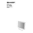
LL-T15A3
CONNECTION, ADJUSTMENT, OPERATION, AND FUNCTIONS
2�2
|
|
|
> |
|