|
|
|
Categories
|
|
Information
|
|
Featured Product
|
|
|
 |
|
|
There are currently no product reviews.
 ;
Wellll again thank you very much fast and effective. Clear and well done for such an old TV!!!!
;
It has all the information you will need to fix it. The main circuit diagram is only A4 but being a PDF, you can print it to any size - I did it on two sheets of A3 and it didnt lose any detail - just made it readable when pinned up above the bench. I've found the fault, just need to buy some obscure bits to get it going again!
I cant fault the process, I paid for the manual in the morning and it was ready to download by lunch time.
 ;
Very good copy in a 54 pages PDF archive. This is my sixth purchase here. :)
;
Another excellent buy! File too clear and explanatory.
;
A manual hard to find. It was very helpful to restore my device.
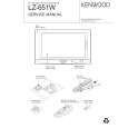
LZ-651W
ADJUSTMENT
No. Adjustment item Measurement point Adjustment part 6 CONTRAST TP204 (G OUT) TEST mode CH13 the white to the negative white is 2.7V ± 0.1V Adjust the amplitude value so that the waveform between 7 Y GAIN TP204 (G OUT) TEST mode CH2 the pedestal to the 10 step signal is 3.1V ± 0.1V Adjust the amplitude value so that the waveform between 8 GAMMA1 TP204 (G OUT) TEST mode CH11 the pedestal to the 3 step signal is 1.4V ± 0.1V Adjust the amplitude value so that the waveform between 9 GAMMA2 TP204 (G OUT) TEST mode CH12 the pedestal to the 10 step signal is 3.2V ± 0.1V Adjust the amplitude value so that the waveform between 10 R SUB BRIGHT TP203 (R OUT) TEST mode CH8 the 1 step signal to the negative 1 step signal is 3.3V ± 0.1V Adjust the amplitude value so that the waveform between 11 B SUB BRIGHT TP205 (B OUT) TEST mode CH9 the 1 step signal to the negative 1 step signal is 3.3V ± 0.1V R SUB 12 CONTRAST B SUB 13 CONTRAST 14 VCOM CN501 16PIN (TP611) TEST mode CH1 7.4V ± 0.1V It adjusts so that the flicker level will be the minimum 15 FLICKER DISPLAY TEST mode CH23 (Auto dimmer off / Bright = max / Zoom mode) The screen of NAVI is made into 2 screen mode. It PICTURE 16 POSITION end of a screen. INPUT VIDEO SIGNAL : 10STEP VIDEO SIGNAL (NTSC 1.0Vp-p) DISPLAY VR501 adjusts so that an active window may come to the right TP205 (B OUT) TEST mode CH15 the white to the negative white is 2.5V ± 0.1V Adjust the amplitude value so that VCOM square wave is Oscilloscope TP203 (R OUT) TEST mode CH14 the white to the negative white is 2.9V ± 0.1V Adjust the amplitude value so that the waveform between Oscilloscope Adjust the amplitude value so that the waveform between Oscilloscope Oscilloscope Oscilloscope Oscilloscope Oscilloscope Oscilloscope Adjustment value Adjust the amplitude value so that the waveform between Oscilloscope Measuring instrument
The definition of video signal and pedestal signal
negative pedestal
negative 1 step
white
negative white 1 step pedestal
9
|
|
|
> |
|