|
|
|
Categories
|
|
Information
|
|
Featured Product
|
|
|
 |
|
|
There are currently no product reviews.
 ;
Please tell us what you think and share your opinions with others. Be sure to focus your comments on the product. You will receive $2.00 of store credit for Your review.
;
Please tell us what you think and share your opinions with others. Be sure to focus your comments on the product. You will receive $2.00 of store credit for Your review.
;
Good copy and great customer service! There was some confusion with my order and it was resolved promptly!
;
Having bought a pre-owned Sony FM stereo tuner through eBay, it came without any manuals. It soon became clear that to get the best from this excellent tuner I needed a decent manual because much of the operation was not intuitive to a newboy to hi fi like me. I managed to download the official Sony multi-lingual manual from Owner-Manuals.com with no problem at all - a really quick and easy service. I'm very glad I did because I found out all the operations of the tuner and was then able to not only set it up quickly but also to get much more from it that poke-and-hope trialling would ever achieve. In my book $4.99 very well spent.
;
This manual is immaculate in it's accuracy. Everything is written very clearly and easy to understand. Written by a professional who wants to convey a clear and easy to understand message!!
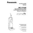
ON-OFF SWITCH REPLACEMENT
Removal
1. Position the handle switch to the off position, remove the handle screw and slide the handle back to free the switch cover tab. 2. Remove the dust cover. Remove the two (2) screws that secure the switch cover, (Fig. 6), then pull straight out on the switch cover to remove it from the dust compartment. 3. Remove the PCB assembly by pulling the circuit boards from the dust compartment. 4. Remove the screw located immediately to the left of the on-off switch. 5. Remove the on-off switch by pulling it straight out, taking care to note the position of the switch lever, for ease of installation.
(Fig. 6)
EXPLODED VIEW (NOZZLE HOUSING)�
A BLOCK
A-19
A-1
A-2 A-7
A-9
A-6
Installation
1. Insert the new on-off switch by placing it back in the reverse manner by which it was removed. Replace the on-off switch screw. Tuck the wire connectors back into the dust compartment. 2. Replace the switch lever and the handle with the on-off switch in the off position, the PCB assembly, switch cover, and the dust cover. Care should be taken not to pinch any wires. NOTE: For general servicing, it is necessary to eliminate pinching of any wire during reassembly. After servicing any electrical component or electrical enclosure, the unit should be reassembled and checked for dielectric breakdown or current leakage.
A-22 A-8 A-23 A-4 A-10 A-21
A-5 A-5 A-27 A-12
SUCTION INLET/HOSE REPLACEMENT
Removal and Replacement
1. Remove the dust cover and dust bag. 2. The inside of the suction inlet/hose is snapped over the inside of the dust compartment. There are four (4) retaining tabs on the suction inlet, (Fig. 8). These four (4) tabs are force fitted into the opening and will have to be broken off using a flat punch and a hammer. Take care to hit only the retaining tabs. Snap the new suction inlet/hose in place. Replace all items removed in the reverse order of removal.
(Fig. 8)
A-15
B BLOCK
A-28
A-11
A-29
Retaining Tabs
Retaining Tabs
A-16 A-16 A-14
A-13
A-20
A-20 A-20 A-20 A-20 A-20 A-3 A-20
A-24
A-25
A-18
A-17
A-26
A-17
- 16 -
-5-
|
|
|
> |
|