|
|
|
Categories
|
|
Information
|
|
Featured Product
|
|
|
 |
|
|
There are currently no product reviews.
 ;
A manual hard to find. It was very helpful to restore my device.
;
I am very grateful for this manual. Without it could not repair my receiver.
;
excellent work as always you do cheap, fast net and clean. you do an incredible service......thanks!
;
Great Job even clear than the one before!!!! god organization- I'm always very satisfied
;
I'm very happy that you all are performing an incredible good job. Furthermore what you did is very useful for all people as me that have electronics as an hobby.Thank you!!!!!
ON-OFF SWITCH REPLACEMENT
Removal
1. Position the handle switch to the off position, remove the handle screw and slide the handle back to free the switch cover tab. 2. Remove the dust cover. Remove the two (2) screws that secure the switch cover, (Fig. 6), then pull straight out on the switch cover to remove it from the dust compartment. 3. Remove the PCB assembly by pulling the circuit boards from the dust compartment. 4. Remove the screw located immediately to the left of the on-off switch. 5. Remove the on-off switch by pulling it straight out, taking care to note the position of the switch lever, for ease of installation.
(Fig. 6)
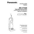
EXPLODED VIEW (NOZZLE HOUSING)�
A BLOCK
A-19
A-1
A-2 A-7
A-9
A-6
Installation
1. Insert the new on-off switch by placing it back in the reverse manner by which it was removed. Replace the on-off switch screw. Tuck the wire connectors back into the dust compartment. 2. Replace the switch lever and the handle with the on-off switch in the off position, the PCB assembly, switch cover, and the dust cover. Care should be taken not to pinch any wires. NOTE: For general servicing, it is necessary to eliminate pinching of any wire during reassembly. After servicing any electrical component or electrical enclosure, the unit should be reassembled and checked for dielectric breakdown or current leakage.
A-22 A-8 A-23 A-4 A-10 A-21
A-5 A-5 A-27 A-12
SUCTION INLET/HOSE REPLACEMENT
Removal and Replacement
1. Remove the dust cover and dust bag. 2. The inside of the suction inlet/hose is snapped over the inside of the dust compartment. There are four (4) retaining tabs on the suction inlet, (Fig. 8). These four (4) tabs are force fitted into the opening and will have to be broken off using a flat punch and a hammer. Take care to hit only the retaining tabs. Snap the new suction inlet/hose in place. Replace all items removed in the reverse order of removal.
(Fig. 8)
A-15
B BLOCK
A-28
A-11
A-29
Retaining Tabs
Retaining Tabs
A-16 A-16 A-14
A-13
A-20
A-20 A-20 A-20 A-20 A-20 A-3 A-20
A-24
A-25
A-18
A-17
A-26
A-17
- 16 -
-5-
|
|
|
> |
|