|
|
|
Categories
|
|
Information
|
|
Featured Product
|
|
|
 |
|
|
There are currently no product reviews.
 ;
Thanks you very much for this "hard to find" service manual.
Will help a lot in repairing this receiver.
;
Thanks you very much for this "hard to find" service manual.
Will help a lot in repairing this receiver.
;
Thanks you very much for this "hard to find" service manual.
Will help a lot in repairing this receiver.
;
Thanks you very much for this "hard to find" service manual.
Will help a lot in repairing this tuner.
;
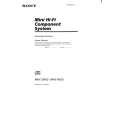
I have this hi-fi system for a long time and I need to repair some things. Founding this manual will be very helpfull :)
CD SECTION
Note: 1. CD Block is basically constructed to operate without adjustment. Therefore, check each item in order given. 2. 3. 4. Use YEDS-18 disc (3-702-101-01) unless otherwise indicated. Use an oscilloscope with more than 10M� impedance. Clean the object lens by an applicator with neutral detergent when the signal level is low than specified value with the following checks. Adjust the focus bias adjustment when optical block is replaced.
RF Level Check
CD DECODER board TP (RF) CN12 (VC) oscilloscope
Procedure : 1. 2. 3. 4. Connect oscilloscope to test point TP (RF) on CD DECODER board. Turned Power switch on. Put disc (YEDS-18) in and playback. Confirm that oscilloscope waveform is clear and check RF
5.
Focus Bias Adjustment
DC voltmeter CD DECODER board CN12 FEO VC
signal level is correct or not. Note: Clear RF signal waveform means that the shape ��� can be clearly distinguished at the center of the waveform.
VOLT/DIV: 200 mV TIME/DIV: 500 nS level: 1.0 �0.2 Vp-p
+0.3
+ �
Procedure: 1. Connect DC voltmeter to test point CN12 (FEO), (VC) on CD DECODER board. 2. Turned Power switch on. 3. Put disc (YEDS-18) in and stop. 4. Adjust VR01 so that the DC voitmeter reading is 0 ± 20 mV. Adjustment Location: CD DECODER board
Adjustment Location: CD DECODER board
Focus Gain Adjustment (VR02) This gain has a margin, so even if it is slightly off. There is no problem. Therfore, do not perform this adjusment. Please note that it should be fixed to mechanical center position when you moved and do not know original position.
Adjustment Location [CD DECODER BOARD] � Component side �
Focus Gain CN12 VR02 IC03 VR01 R07 Focus Bias IC01 RF Level
� 13 �
|
|
|
> |
|