|
|
|
Categories
|
|
Information
|
|
Featured Product
|
|
|
 |
|
|
There are currently no product reviews.
 ;
The ervice manual for my 1982 Kenwood KR-1000 receiver is great! Full detail on all circuits with part number detail. I will definately be ordering more manuals for my other vintage equipment! Order was fulfilled quickly! Very efficient ordering process! Thnaks for your help! Great site!
 ;
Everything in the manual was excellent except for a couple of pictures of specific areas in the unit that were a little dark. Owners Manuals re-sent the pdf file & the problem was corrected. Excellent product! George
;
Thanks for offering this item at such a good price. Proved handy in identifying the part I was looking for my set.
Thanks again.
;
This is the original manufacturers service manual, with detailed info on the circit boards, explosion drawings of all parts in assembly order, and tuning instructions. The only thing missing is the information on the dimensions of the various drive belts. mail me if you need them. gcrossman_at_aol.com
;
Ordered service manuel for a hard to find plasma tv - your company made it easy to find and purchase - I will use you again
Thanks for your help
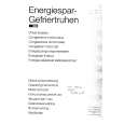
With Iron Wire: 1. Using desoldering braid, remove the solder from all pins of the flat pack-IC. When you use solder flux which is applied to all pins of the flat pack-IC, you can remove it easily. (Fig. S-1-3) 2. Affix the wire to a workbench or solid mounting point, as shown in Fig. S-1-5. 3. While heating the pins using a fine tip soldering iron or hot air blower, pull up the wire as the solder melts so as to lift the IC leads from the CBA contact pads as shown in Fig. S-1-5. 4. Bottom of the flat pack-IC is fixed with glue to the CBA; when removing entire flat pack-IC, first apply soldering iron to center of the flat pack-IC and heat up. Then remove (glue will be melted). (Fig. S-1-6) 5. Release the flat pack-IC from the CBA using tweezers. (Fig. S-1-6) Note: When using a soldering iron, care must be taken to ensure that the flat pack-IC is not being held by glue. When the flat pack-IC is removed from the CBA, handle it gently because it may be damaged if force is applied.
2. Installation
1. Using desoldering braid, remove the solder from the foil of each pin of the flat pack-IC on the CBA so you can install a replacement flat pack-IC more easily. 2. The ��� mark on the flat pack-IC indicates pin 1. (See Fig. S-1-7.) Be sure this mark matches the 1 on the PCB when positioning for installation. Then presolder the four corners of the flat pack-IC. (See Fig. S-1-8.) 3. Solder all pins of the flat pack-IC. Be sure that none of the pins have solder bridges.
Example :
Hot Air Blower
Pin 1 of the Flat Pack-IC is indicated by a " " mark.
Fig. S-1-7
or Iron Wire
Presolder
Soldering Iron To Solid Mounting Point Fig. S-1-5 Flat Pack-IC CBA CBA Fine Tip Soldering Iron Fig. S-1-8
Flat Pack-IC Tweezers Fig. S-1-6
3-3
TVN_SN
|
|
|
> |
|