|
|
|
Categories
|
|
Information
|
|
Featured Product
|
|
|
 |
|
|
There are currently no product reviews.
 ;
Do a quick order, scan quality is high.
I recommend to all!
;
This manual is perfect! Just what I needed. Thanks!
;
This manual was very clear and complete, the prices can't be beat, great to have older manuals available!
 ;
Doubted for buy this manual as it is my first order here and at not have cover image, I assumed would haven't. However, within 24 hs, already possessed the link to download it. The manual are scanned correctly and have all what is needed. Includes adjustments and diagrams of all circuits. Very satisfied.
;
Really good quality, аll readable.! Wonderful work shop. I recommend to all!
2-1
2-1
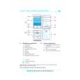
DISMANTLING INSTRUCTIONS
Dismantling of the Front Panel assembly 1) Loosen the 9 screws to dismantle the Top Cover (pos 252) - 2 screws on each side - 5 screws on the Rear Panel (pos 251). 2) Loosen 5 screws A and 8 catches C1 to slide the Front Panel assembly (pos 101, 102, 103, etc) as per figure 1. Note: To remove the Source / Volume control pc board (pos 1105B) 2 nuts hidden below the control knob assembly (pos 133, 134 and 135) must first be removed. 3) Loosen bracket (pos 254) by turning a catch, sliding towards the outside and lifting it upwards as per figure 5.
D
Dismantling the Tuner, Mains and AV boards 1) Loosen 3 screws D and 2 catches C2 on the Rear panel (pos 251) to remove the Tuner board assemby (pos 1101) as pe figure 3. 2) Loosen 1 screws E and 2 catches C3 to unslot the Mains board (pos 1102-A) out of the Rear panel as per figure 4. 4) Loosen 8 screws F (7 screws for non-Scart version) and 2 catches C5 to separate Rear Plate assembly (pos 251) from the Bottom plate assembly (pos 227) as per figure 3. 5) Uncatch C4 to remove the AV board (pos 1104) from the Bottom Plate assembly (pos 227) as per figure 5.
C1
C1
C1
C1
A A
C1
A
C1
C5
C2 C5
A
C1
Figure 1
A
F
C1
Figure 3
F
2 1
Hints for re-assembly of Top Cover Due to appearance design the Top cover (pos 252) is sandwiched between the Front panel (pos 101) and the 2 side covers (pos 102 & 103), this make it necessary to remove the 2 side covers before re-assembly of Top cover. 1) To remove the side cover use a small screw driver with marking 16mm from the tip end. 2) Insert the screw driver into slot (as shown in figure 2) and push the tip outwards to release the side cover catch. The side cover can be pull outwards as soon as the top catch is released.
C4
Turn up the lever, slide the bracket as shown and lift out of the bottom chassis.
Figure 4 Figure 5
Dismantling the Supply & Power Amplifier boards 1) Loosen 2 screws B mounting the Supply board's (pos 1102-B) heatsink to the Bottom Plate (pos 227) as per figure 6. Note: During re-assembly care must be taken to ensure the Mains Transformer wires to the Supply board is routed properly below the board. 2) Loosen 4 screws C to dismantle the Power Amplifier board (pos 1102-D) from the Bottom Plate as per figure 6. Figure 2 Figure 6
|
|
|
> |
|