|
|
|
Categories
|
|
Information
|
|
Featured Product
|
|
|
 |
|
|
There are currently no product reviews.
 ;
This was an excellent source of detailed assembly information on a device which is at least 12 years old. A very lucky find, coupled with great service.
;
Excellent Service Manual and best price on the Internet. This Service Manual covers everything you could ever need including full circuit schematics, component layout diagrams, stripdown procedure and full parts list/breakdown. I needed this to carry out a modification to one of these headunits and this manual covered everything I needed. Fast delivery, processed within a few hours.
 ;
Thought I would never find a copy of the Technics SX-EN2 Service Manual until I found Owner-Manuals.com. Price was very fair and I received the download promptly. While a photocopy, it is quite readable and includes all the pertinent information and diagrams. Thank you Owner-Manuals!
;
I really like this manual and it's reliable.I found and bought easly.thank you.
;
Thank you very much. the Instruction corresponds to my expectations. Sent it in time. I don't regret that paid money.
MX-DVA5
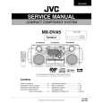
Removing the tuner board (See Fig.11 and 13)
Prior to performing the following procedure, remove the metal cover and CD / DVD changer unit. 1. Disconnect the card wire from connector CON01 on the tuner board. 2. Remove the two screws L attaching the tuner board.
CON01
Rear panel
Main board
Tuner board
Fig.13
Removing the rear panel
(See Fig.14)
Prior to performing the following procedure, remove the metal cover, CD / DVD changer unit, heat sink & Amp. board and tuner board. 1. Remove the three screws N and five screws M attaching the rear panel.
Rear panel
M N
Fig.14
Removing the main Board (See Fig. 15)
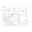
Prior to performing the following procedure, remove the metal cover, CD / DVD changer unit, heat sink & Amp. board tuner board and rear panel. 1. Disconnect the card wire from connector FCW3 and the harness from connector JCW1, JCW2, and HCW3 on the main board. 2. Disconnect the harness from connector PCW1 on the power transformer board. 3. Remove the screw G attaching the main board holder. (See Fig.8) 4. Remove the two screws O attaching the heat sink and bottom chassis.
PCW1 Power transformer board FCW3 JCW2 JCW1 HCW3 Main board
O
Fig.15
1-9
 $4.99 MX-DVA5 JVC
Parts Catalog Parts Catalog only. It's available in PDF format. Useful, if Your equipment is broken and You need t…
|
|
|
> |
|