|
|
|
Categories
|
|
Information
|
|
Featured Product
|
|
|
 |
|
|
There are currently no product reviews.
 ;
This manual is a complete guide, including later additions. It has all the necessary information about the replacement items. The material quality is great to read.
 ;
This manual is very helpful, correct shematic diagram, and good exploded view.Perfect!
;
Alte gescannte Servicepläne sind oft doch etwas undeutlich . Stromlaufpläne werden auf mehrere DIN A4 Seiten aufgeteilt. Alles ziemlich umständlich und zeitaufwendig. Aber mit etwas Mühe geht alles.
;
Great item, high resolution, detailed, very easy to work with.
;
fast delevery of the manual and very complete manual, now my Akai works again, will buy again, thanks.
SECTION 2 SELF-DIAGNOSTIC
2-1. GENERAL
This set uses the self-diagnostic system in which if an error occurs in playback/recording mode, the error is detected by the model control and power control blocks of the microprocessor and information on the cause is stored as history in EEPROM. By viewing this history in test mode, it helps you to analyze a fault and determine its location. 2) Remote controller LCD
888
ı
All ON
2-2. TEST MODE SETTING
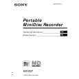
There are two different methods to set the test mode: 1 Short BP801 (TEST) on the main board with a solder bridge (connect pin @§ of IC801 to the ground). Then, turn on the power.
MAIN BOARD (SIDE B)
All OFF
Vr. 1.��
Microprocessor version display
X801
IC801
� Holding down P allows the current display to be maintained while it being depressed.
2-4. RELEASING THE TEST MODE
25 26
For test mode set with the method 1: Turn off the power and open the solder bridge on BP801 on the main board. For test mode set with the method 2: Turn off the power.
BP801 (TEST) IC301
C401
2-5. SELF-DIAGNOSTIC MODE
1. Go into the test mode. 2. With the unit LCD indicators all flashing, press DISPLAY key to go into the self-diagnostic mode.
2 In the normal mode, use the keys on the unit to perform the following operations: Press and hold down ( and press the keys below in this turn: + n + n =n = n + n = n + n =nPnP
1st0 00
2-3. OPERATION IN TEST MODE SETTING
When the test mode is set, the LCD shows repeated cycles of the following display: 1) Unit LCD
Error indication code History code
3. Then, each time ) key is pressed, the reference information display changes as given below.
1st
� 1 2 � 1 2
XX �� �� XX �� ��
N-1 N-1 N-1 N-2 N-2 N-2 R 1st
� 1 2 � 1 2
XX �� �� XX �� �� XXXX
ı 188:88 pppppp
All ON
1st 1st
All OFF
N N
Microprocessor version display
N
Vr. 1.00
�
XX
(return)
� Press = key to go back to the previous display.
�5�
 $4.99 MZR37 SONY
Owner's Manual Complete owner's manual in digital format. The manual will be available for download as PDF file aft…
|
|
|
> |
|