|
|
|
Categories
|
|
Information
|
|
Featured Product
|
|
|
 |
|
|
There are currently no product reviews.
 ;
Great Job even clear than the one before!!!! god organization- I'm always very satisfied
;
I'm very happy that you all are performing an incredible good job. Furthermore what you did is very useful for all people as me that have electronics as an hobby.Thank you!!!!!
;
Manual found fast and good quality, very helpfull service
;
8-17-12 Been using the sight for about 6 months. Fast Downloads and top quality
Manuels !
 ;
Everything was great, the manual, the response time, the simplicity of the order, and the
Price. The only thing that I could possible say on a negative note would be that the manual I ordered was more for a service tech. There were a lot of schematic diagrams that didn't help me solve the problem. However I would order again and recommend the web sight to others.
5
6
7
8
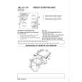
3 X CONNECTOR A Assy, B Assy, 43 SCAN A Assy and B Assy
X CONNECTOR A and B Assy
Remove the one screw. Note: Be sure to remove this screw. If you don't, the connector on the LED OPT Assy may be damaged.
A
1 2 3 4
Remove the one nylon rivet.
6
6
43 X DRIVE Assy
6
Remove the LED OPT Assy.
6 5
Front chassis VR (43M) Flat clamp
6
Bottom view
Remove the enclosure sheet 1. Note: Enclosure sheet 1 is attached to comply with the safety standards. Make sure that it will not be shifted or peeled off. If it is peeled off, securely reattach it in its original place.
1
2
B
5 6
Remove the jumper wire by removing the flat clamp. Remove the front chassis VR (43M) by removing the five screws.
4
Enclosure sheet 1
3
LED OPT Assy
7 8
Remove the six screws. Remove the X CONNECTOR A and B Assy.
43 X DRIVE Assy
7
�2
7
�4
C
Note when reassembling the front chassis VR (43M) Remove or loosen the screws that secure the panel holder in order not to damage the front protect panel Assy.
8
X CONNECTOR B Assy
8
X CONNECTOR A Assy
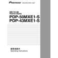
43 SCAN A and B Assy
1 2 3 4
Remove the one nylon rivet. Remove the jumper wire by removing the flat clamp. Remove the one screw. Remove the front chassis VL (43M) by removing the five screws.
4
4
43 Y DRIVE Assy
4
D
4
Front chassis VL (43M)
Flat clamp
4 2
3
1
E
5 6 7 8 9
Remove the four screws. Disconnect the two pin connectors. Remove the two spacers. Remove the four spacers. Remove the 43 SCAN A and B Assy. 43 Y DRIVE Assy
5 6 8 9
�2
5 8 8 7
�2
6 7 8 9
43 SCAN A Assy
F
Note when reassembling the front chassis VL (43M) Remove or loosen the screws that secure the panel holder in order not to damage the front protect panel Assy.
43 SCAN B Assy
PDP-434CMX
5 6 7 8
113
|
|
|
> |
|