|
|
|
Categories
|
|
Information
|
|
Featured Product
|
|
|
 |
|
|
There are currently no product reviews.
 ;
The quality of this manual is good. It has all schematics and setup information for both the MDS-B3 and the MDS-B4. The scan quality is quite good, all pages are readable, This service manual also contains scans of the operating instructions from the User manual.
 ;
Quick site processing. A complete and very useful manual with all details. Thank you!
;
Das Service Manual war von der ersten bis zur letzten Seite sehr informativ und hilfreich. Die Darstellung aller Teile war klar und der Text gut lesbar.
Vielen Dank, das war nicht der letzte Download bei ownner-manuals.com.
;
It's a grate service manuals.Have many details and the writing it's so clear.You have all you want in manual,nothing missing,belive me.I'm verry satisfied of this manual.
;
Great scanned service manual
Usefull informations.
I will buy again!
Best Regards
5
6
7
8
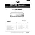
6.2 ADJUSTMENT REQUIRED WHEN THE SET IS REPAIRED OR REPLACED
INTERFACE Assy
When repaired
No adjustment required.
Y DRIVE Assy
When repaired
Note: If the Pulse Module fails, it is not possible to repair the Y DRIVE Assy by replacing only the Pulse Module. Replace the entire Y DRIVE Assy. � VOFS/VH/IC5V voltage adjustment
A
When replaced
No adjustment required.
When replaced
SW POWER SUPPLY Module
When replaced
No adjustment required.
� Panel white balance adjustment
X DRIVE Assy
When repaired
B
DIGITAL VIDEO Assy
When repaired
No adjustment required.
Note: If the Pulse Module fails, it is not possible to repair the X DRIVE Assy by replacing only the Pulse Module. Replace the entire X DRIVE Assy. � VRN voltage adjustment
When replaced
1. Remove IC1204 (24LC04(1) SN-TBB) from the former PC Board to replace, and install it to the new PC Board. 2. When use new Assy which replaces it and recovered as service parts once again, replace IC1204 with new IC.
When replaced
� Panel white balance adjustment
C
SW POWER SUPPLY Module
D
Y DRIVE Assy
X DRIVE Assy
E
DIGITAL VIDEO Assy
INTERFACE Assy
Fig. 1 PC Board Location (rear side view)
F
PDU-50WX2A
5 6 7 8
49
|
|
|
> |
|